Suzuki Grand Vitara JB416 / JB420. Manual - part 167


  Index      Suzuki     Suzuki Grand Vitara JB416 / JB420- service repair manual


Search            


Content   ..  165  166  167  168   ..


Suzuki Grand Vitara JB416 / JB420. Manual - part 167


3B-21 Differential: Rear

Rear

General Description

Rear Differential Construction

S5JB0A3221001

Refer to “Front Differential Construction: Front”.

Diagnostic Information and Procedures

Rear Differential Symptom Diagnosis

S5JB0A3224001

Refer to “Front Differential Symptom Diagnosis: Front”.

Repair Instructions

Rear Differential Oil Change

S5JB0A3226010

Refer to “Front Differential Oil Change: Front”.
The point which is different from the front differential is described.

Rear differential oil capacity
Reference: 0.8 – 0.9 liters (1.7/1.4 – 1.9/1.6 US/Imp. pt.)

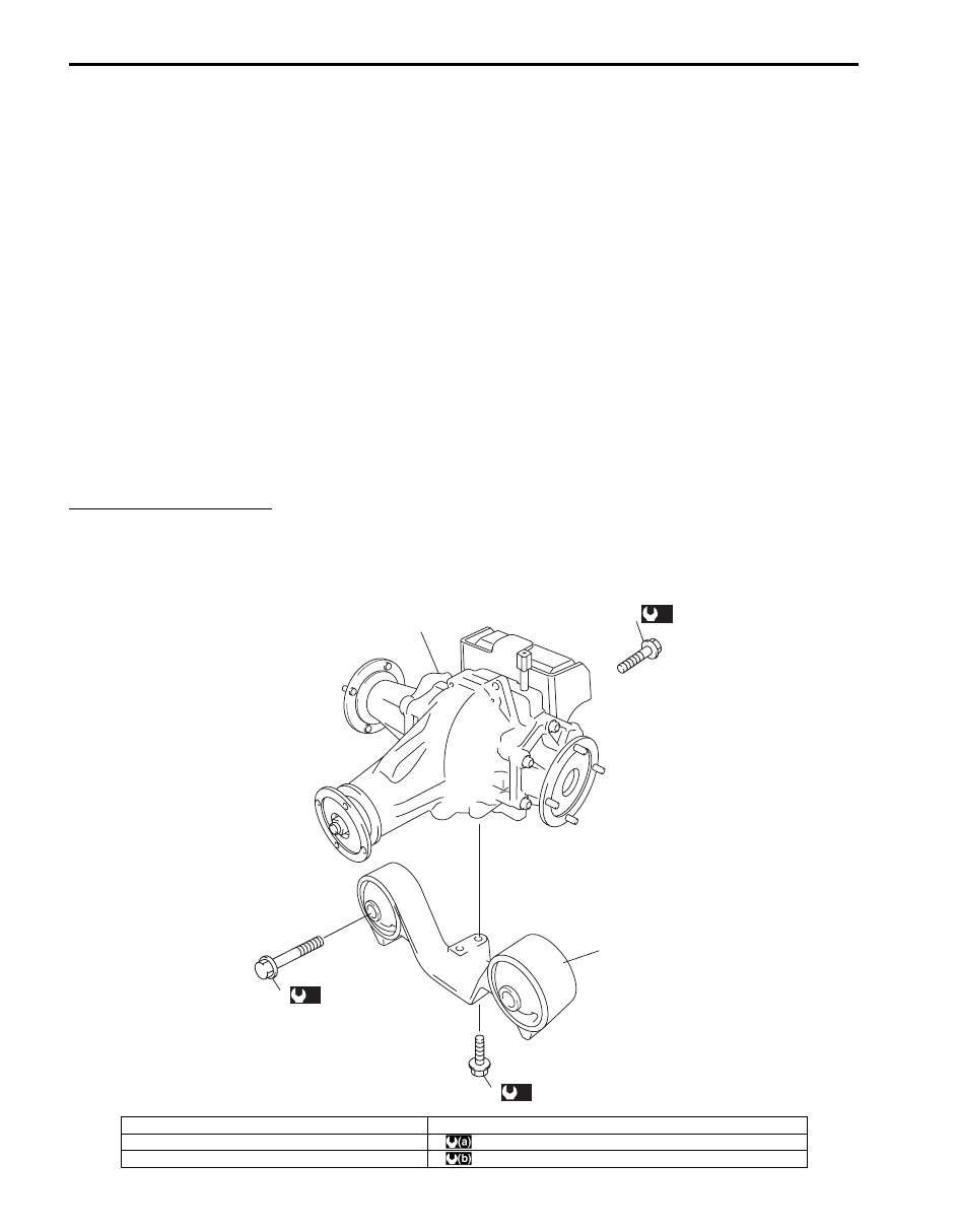
Rear Differential Unit Components

S5JB0A3226011

(a)

4

(a)

3

(b)

5

1

2

I5JB0A322002-03

1. Rear differential

4. Front mounting bracket bolt

2. Front mounting bracket

: 120 N

⋅m (12.0 kgf-m, 87.0 lb-ft)

3. Rear mounting bolt

: 50 N

⋅m (5.0 kgf-m, 36.5 lb-ft)

Differential: Rear 3B-22

Rear Differential Dismounting and Remounting

S5JB0A3226012

Dismounting

1) Lift up vehicle and drain oil from rear differential.
2) Remove rear propeller shaft referring to “Propeller 

Shaft Removal and Installation in Section 3D”.

3) Remove exhaust center pipe referring to “Exhaust 

System Components in Section 1K”.

4) Remove rear drive shafts referring to “Rear Drive 

Shaft Assembly Removal and Installation: Rear in 
Section 3A”
.

5) Dismount rear differential as follows.

• For M16 engine model

a. Remove fuel tank cover (1).

b. Support rear differential with transmission 

jack.

c. Loosen rear differential mounting front bolts 

(1) and rear bolts (2).
Do not remove them in this step.

d. Remove rear suspension frame mount front 

bolts (1).

WARNING

!


Do not loosen rear suspension frame rear 
bolts more than 8 turns. Otherwise, rear 
suspension frame may fall and cause 
personal injury.


e. Loosen rear suspension frame mount rear 

bolts gradually within 8 turns until rear 
differential mounting front bolts can be 
removed.

f.

Remove rear differential mounting front and 
rear mounting bolts, and then lower rear 
differential.

g. Tighten temporarily rear suspension frame 

mount front and rear bolts.

• For J20 engine model

a. Support rear differential with transmission 

jack.

b. Remove front and rear mounting bolts, and 

then lower rear differential.

1

I5JB0A322006-01

1

2

I5JB0A322003-01

1

I5JB0A322004-01

1

I5JB0A322005-01

3B-23 Differential: Rear

Remounting
Reverse dismounting procedure for remounting noting 
the following.
• Tighten rear differential mounting front and rear bolts 

to specified torque.

Tightening torque
Rear differential front mounting bolt:  120 N·m (
12.0 kgf-m, 87.0 lb-ft)
Rear differential rear mounting bolt:  120 N·m (
12.0 kgf-m, 87.0 lb-ft)

• Tighten rear suspension frame front and rear bolts to 

specified torque referring to “Rear Suspension 
Construction in Section 2C”
.

• Fill rear differential oil referring to “Rear Differential Oil 

Change: Rear”.

Rear Differential Components

S5JB0A3226001

2

10

10

12

(a)

18

(a)

18

(b)

24

19

9

21

11

5

28

13

23

20

12

(c)

22

3

4

6

7

A

8

1

(a)

25

26

12

11

27

17

16

14

14

16

17

15

20

15

I5JB0A322001-09

1. Universal joint flange

18. Retainer bolt

2. Hypoid gear set

19. Rear drive right retainer

: Apply sealant 99000-31260 to mating surface of right retainer, carrier 
and rear cover.

3. Bevel pinion spacer

20. Shim

4. Shim

21. Rear drive left retainer

: Apply sealant 99000-31260 to mating surface of left retainer, carrier 
and rear cover.

5. Rear bearing

22. Bevel gear bolt

: Apply thread lock cement 99000-32110 to thread part of bolt.

6. Front bearing

23. Rear cover

 7. Oil seal

: Apply grease 99000-25010 to oil seal lip.

24. Rear cover bolt No.2 bolt

Differential: Rear 3B-24

Rear Differential Assembly Disassembly and 
Reassembly

S5JB0A3226013

Disassembly

1) Drive out rear drive right and left shaft using special 

tools.

Special tool
(A):  09942–15511 
(B):  09943–17912 

2) Remove rear drive right and left retainers.
3) Tapping rear cover flanges with plastic hammer, 

remove rear cover (1) and dynamic damper (if 
equipped).

4) Disassembly rear drive right retainer as follows, if 

necessary.
a) Remove oil seal (1) using special tool.

Special tool
(A):  09913–50121 

b) Remove snap ring.

c) Drive out rear drive shaft bearing using special 

tools.

Special tool
(A):  09930–30104 
(B):  09941–64511 

 8. Flange nut

: After tightening nut so as rotation torque of bevel pinion shaft to 
be in specified value, caulk nut securely.

25. Rear cover bolt No.1 bolt

9. Differential carrier

26. Dynamic damper (if equipped)

10. Differential pinion

27. Pinion joint

11. Differential gear

28. Differential right case

12. Pinion shaft

: 50 N

⋅m (5.0 kgf-m, 36.5 lb-ft)

13. Differential left case

: 60 N

⋅m (6.0 kgf-m, 43.5 lb-ft)

14. Thrust washer

: 40 N

⋅m (4.0 kgf-m, 29.5 lb-ft) + 50°

15. Differential side bearing

: Do not reuse.

16. Spring washer

: Apply differential oil.

17. Pinion washer

(A)

(B)

I5JB0A322007-01

1

I5JB0A322008-01

(A)

1

I5JB0A322009-01

I5JB0A322010-01

(A)

(B)

I5JB0A322011-01


Content   ..  165  166  167  168   ..