Suzuki Grand Vitara JB416 / JB420. Manual - part 84


  Index      Suzuki     Suzuki Grand Vitara JB416 / JB420- service repair manual


Search            


Content   ..  82  83  84  85   ..


Suzuki Grand Vitara JB416 / JB420. Manual - part 84


1D-4 Engine Mechanical: For M16A Engine with VVT

Targeted Timing Varying Operation

Diagnostic Information and Procedures
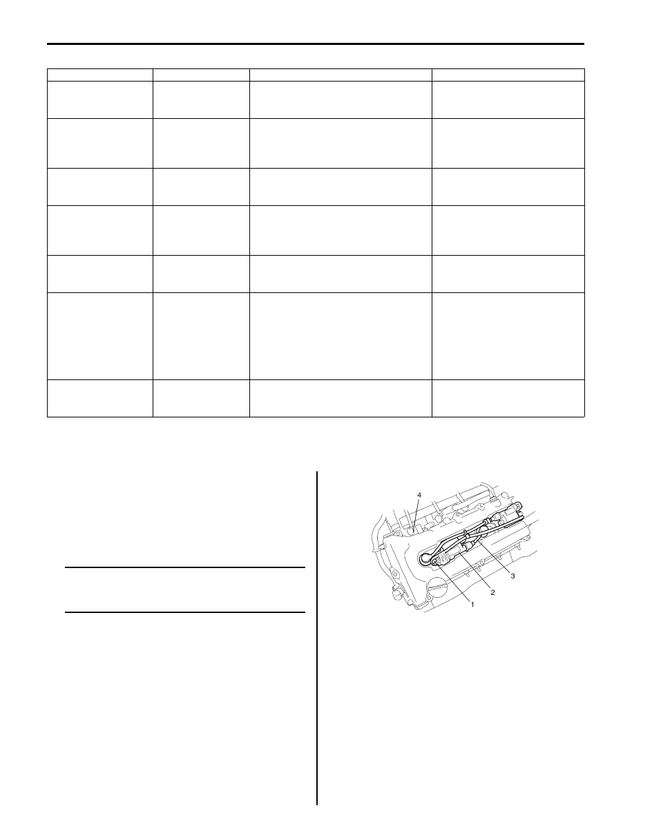
Compression Check

S5JB0A1414001

Check compression pressure on all 4 cylinders as 
follows:

1) Warm up engine to normal operating temperature.
2) Stop engine after warming up.

NOTE
After warming up engine, place transaxle 
gear shift lever in “Neutral”, and set parking 
brake and block drive wheels.


3) Disconnect ignition coil couplers (1).
4) Remove ignition coil assemblies (2) with high-

tension cord (3).

5) Remove all spark plugs.
6) Disconnect fuel injector wires (4) at the coupler.

Driving condition

Valve timing

Target of control

Effect

Engine running at idle 
speed

Most retarded

To shorten the valve opening overlap in 
order to prevent the exhaust gas 
counterflow to intake manifold.

Stabilization of the engine 
rotation at idle speed.

Average engine load 
range

To the advanced 
side

To lengthen the valve opening overlap 
in order to enhance the internal 
exhaust gas recirculation and reduce 
the pumping loss.

Improvement of the fuel 
efficiency.
Lowering of the exhaust 
emission.

Light engine load 
range

To the retarded side

To shorten the valve opening overlap in 
order to prevent the exhaust gas 
counterflow to intake manifold.

Keeping of the engine stability.

Low or average 
engine speed range 
with heavy engine 
load

To the advanced 
side

To advance the closing timing of the 
intake valve in order to improve the 
volumetric efficiency.

Improvement of generating the 
engine torque at low and 
average engine speed.

High engine speed 
range with heavy 
engine load

To the retarded side

To retard the closing timing of the 
intake valve in order to improve the 
volumetric efficiency.

Improvement of generating the 
engine power.

Low engine coolant 
temperature

Most retarded

To shorten the valve opening overlap in 
order to prevent the exhaust gas 
counterflow to intake manifold and 
reduce the fuel increasing.
To slow the fast idle speed of the 
engine as a result of stabilizing the 
engine idling.

Stabilization of the fast idling of 
the engine.
Improvement of the fuel 
efficiency.

At engine starting and 
stopping

Most retarded

To shorten the valve opening overlap in 
order to prevent the exhaust gas 
counterflow to intake manifold.

Improvement of start ability.

I2RH0B140003-01

Engine Mechanical: For M16A Engine with VVT 1D-5

7) Install special tools (Compression gauge) into spark 

plug hole.

Special tool
(A):  09915–64512
(B):  09915–64530
(C):  09915–67010

8) Disengage clutch (to lighten starting load on engine) 

for M/T vehicle, and depress accelerator pedal (1) all 
the way to make throttle fully open.

9) Crank engine with fully charged battery, and read the 

highest pressure on compression gauge.

NOTE

• For measuring compression pressure, 

crank engine at least 250 r/min. by using 
fully charged battery.

• If measured compression pressure is 

lower than limit value, check installation 
condition of special tool. If it is properly 
installed, possibility is compression 
pressure leakage from where piston ring 
and valve contact.


Compression pressure
Standard: 1400 kPa (14.0 kg/cm

2

, 199.0 psi)

Limit: 1100 kPa (11.0 kg/cm

2

, 156.0 psi)

Max. difference between any two cylinders: 100 
kPa (1.0 kg/cm

2

, 14.2 psi)

10) Carry out Steps 7) through 9) on each cylinder to 

obtain 4 readings.

11) After checking, install spark plugs and ignition coil 

assemblies (2) with high-tension cord (3).

12) Connect ignition coil couplers (1).

13) Connect fuel injector wires (4) at the coupler.

Engine Vacuum Check

S5JB0A1414002

The engine vacuum that develops in the intake line is a 
good indicator of the condition of the engine. The 
vacuum checking procedure is as follows:

1) Warm up engine to normal operating temperature.

NOTE
After warming up engine, be sure to place 
transaxle gear shift lever in “Neutral”, and set 
parking brake and block drive wheels.


2) Stop engine and turn off the all electric switches.
3) Remove PCV hose (1) from PCV valve (2).

4) Connect special tool (Vacuum gauge) to PCV hose 

(1).

Special tool
(A):  09915–67311

5) Blind PCV valve (2) using tape or the like.

(A)

(C)

(B)

I3RH0B140009-01

I5JB0A141001-02

I2RH0B140003-01

1

2

I5RS0D140013-01

(A)

1

2

I5JB0A141002-02

1D-6 Engine Mechanical: For M16A Engine with VVT

6) Run engine at specified idle speed and read vacuum 

gauge. Vacuum should be within specification.

Vacuum specification (at sea level)
59 – 73 kPa (45 – 55 cmHg, 17.7 – 21.6 in.Hg) at 
specified idle speed

7) After checking, disconnect special tool (Vacuum 

gauge) from PCV hose.

8) Detach blind cap from PCV valve.
9) Connect PCV hose to PCV valve.

Valve Lash (Clearance) Inspection

S5JB0A1414003

1) Remove negative cable at battery.
2) Remove cylinder head cover referring to “Cylinder 

Head Cover Removal and Installation: For M16A 
Engine with VVT”.

3) Using 17 mm wrench, turn crankshaft pulley (1) 

clockwise until cam lobes (2) become perpendicular 
to shim faces (3) at valves “1” and “7” as shown in 
the figure.

4) Check valve lashes with thickness gauge (4) 

according to the following procedure.
a) Check valve lashes at valves “1” and “7”.
b) Turn camshafts by 90

° (by turning crankshaft 

with wrench).

c) Make sure that cam lobes are perpendicular to 

shim faces at valves to be checked (in this case, 
“3” and “8”), if not, adjust it by turning crankshaft. 
Check valve lashes.

d) In the same manner as b) – c), check valve 

lashes at valves “4” and “6”.

e) In the same manner as b) – c) again, check 

valve lashes at valves “2” and “5”.

If valve lash is out of specification, record valve lash and 
adjust it to specification by replacing shim.

Valve clearance specification
When cold (Coolant temperature is 15 – 25 

°C (59 – 

77 

°F)):

• Intake: 0.18 – 0.22 mm (0.007 – 0.009 in.)
• Exhaust: 0.28 – 0.32 mm (0.011 – 0.013 in.) 

When hot (Coolant temperature is 60 – 68 

°C (140 – 

154 

°F)):

• Intake: 0.21 – 0.27 mm (0.008 – 0.011 in.) 
• Exhaust: 0.30 – 0.36 mm (0.012 – 0.014 in.)

Replacement of Shim

1) Close the valve whose shim (2) is to be replaced by 

turning crankshaft, then turn tappet (3) till its cut 
section (1) faces inside as shown in the figure.

I3RM0A140004-01

I2RH0B140006-01

Engine Mechanical: For M16A Engine with VVT 1D-7

2) Lift down the valve by turning crankshaft to 360

°.

3) Hold tappet at that position using special tool as 

follows.
a) Remove its housing bolts.
b) Check housing No. and select special tool 

corresponding to housing No., referring to 
“Special tool selection table”.

Special tool selection table

c) Hold down the tappet so as not to contact the 

shim by installing special tool on camshaft 
housing with housing bolt (1) tighten housing 
bolts to specified torque.

Special tool
(A):  09916–67020
(A):  09916–67021

Tightening torque
Camshaft housing bolts (a):  8 N

m (0.8 kgf-

m, 6.0 lb-ft) for tightening of special tool

4) Turn camshaft by approximately 90

° clockwise and 

remove shim (3).

WARNING

!


Never put in the hand between camshaft and 
tappet.


5) Using a micrometer (2), measure the thickness of 

the removed shim (1), and determine replacement 
shim by calculating the thickness of new shim with 
the following formula and table.

Shim thickness specification
Intake side:
A = B + C – 0.20 mm (0.008 in.)
Exhaust side:
A = B + C – 0.30 mm (0.012 in.)
A: Thickness of new shim
B: Thickness of removed shim
C: Measured valve clearance

For example of intake side:
When thickness of removed shim is 2.40 mm (0.094 
in.), and measured valve clearance is 0.45 mm 
(0.018 in.).
A = 2.40 mm (0.094 in.) + 0.45 mm (0.018 in.) – 0.20 
mm (0.008 in.) = 2.65 mm (0.104 in.) 
Calculated thickness of new shim = 2.65 mm (0.104 
in.)

No. on camshaft 

housing

Embossed mark on 

special tool

I2

IN2

I3, I4, I5

IN345

E2

EX2

E3, E4, E5

EX345

A: I: Intake side or E: Exhaust side
B: Position from timing chain side

C: Pointing to timing chain side

I2RH0B140011-01

I3RM0A140005-01

1. Special tool

2. Magnet

I2RH0B140013-01

I2RH0B140014-01


Content   ..  82  83  84  85   ..