Suzuki Grand Vitara JB416 / JB420. Manual - part 70


  Index      Suzuki     Suzuki Grand Vitara JB416 / JB420- service repair manual


Search            


Content   ..  68  69  70  71   ..


Suzuki Grand Vitara JB416 / JB420. Manual - part 70


1A-229 Engine General Information and Diagnosis: 

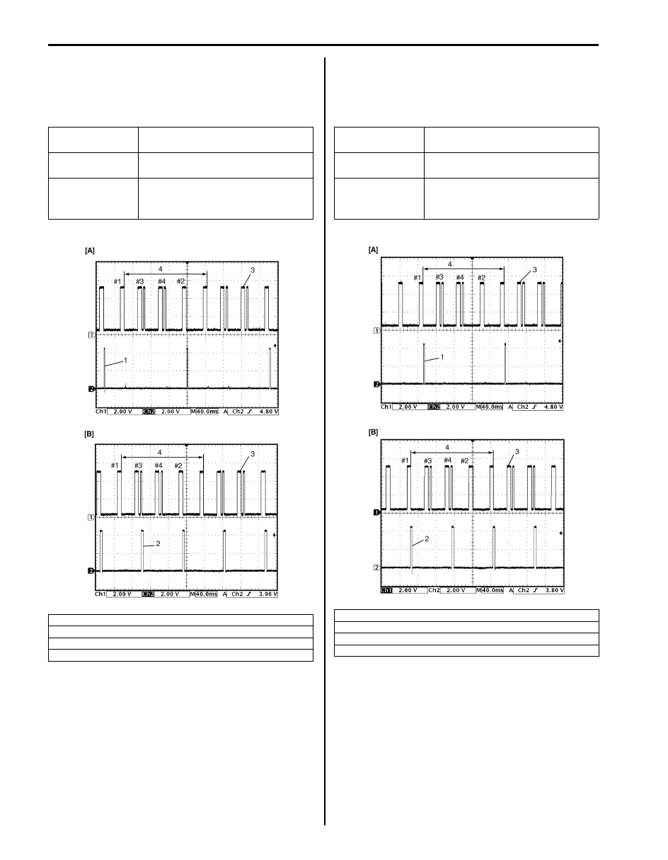
Reference waveform No.15
• Ignition coil No.2 signal (1) with engine idling (for J20 

engine)

• Ignition coil No.2 and No.3 signal (2) with engine idling 

(for M16 engine)

Reference waveform No.16
• Ignition coil No.1 signal (1) with engine idling (for J20 

engine)

• Ignition coil No.1 and No.4 signal (2) with engine idling 

(for M16 engine)

Measurement 
terminal

CH1: “C37-52” to “C37-58”
CH2: “C37-20” to “C37-58”

Oscilloscope 
setting

CH1: 2 V/DIV, CH2: 2 V/DIV
TIME: 40 ms/DIV

Measurement 
condition

• After warmed up to normal 

operating temperature

• Engine at specified idle speed

[A]: For J20 engine
[B]: For M16 engine

3. Cylinder reference signal (CMP reference signal)
4. 720

° crank angle

I5JB0A110086-01

Measurement 
terminal

CH1: “C37-52” to “C37-58”
CH2: “C37-21” to “C37-58”

Oscilloscope 
setting

CH1: 2 V/DIV, CH2: 2 V/DIV
TIME: 40 ms/DIV

Measurement 
condition

• After warmed up to normal 

operating temperature

• Engine at specified idle speed

[A]: For J20 engine
[B]: For M16 engine

3. Cylinder reference signal (CMP reference signal)
4. 720

° crank angle

I5JB0A110087-02

Engine General Information and Diagnosis:  1A-230

Reference waveform No.17
Mass air flow sensor signal (1) with engine racing

Reference waveform No.18
A/F sensor signal with engine idling

Reference waveform No.19
Intake manifold tuning vacuum solenoid valve signal with 
engine racing (for J20 engine)

Measurement 
terminal

CH1: “C37-26” to “C37-27”
CH2: “C37-54” to “C37-41”

Oscilloscope 
setting

CH1: 1 V/DIV, CH2: 1 V/DIV
TIME: 200 ms/DIV

Measurement 
condition

• After warmed up to normal 

operating temperature

• Engine racing

2. Throttle position sensor (main) signal
3. Racing
4. Idle

Measurement 
terminal

CH1: “C37-38” to “C37-58”
CH2: “C37-37” to “C37-58”
CH3: “C37-32” to “C37-31”

Oscilloscope 
setting

CH1: 500 mV/DIV, CH2: 500 mV/
DIV, CH3: 10 V/DIV
TIME: 100 ms/DIV

Measurement 
condition

• After warmed up to normal 

operating temperature

• Engine at specified idle speed

1. A/F sensor signal (+)
2. A/F sensor signal (–)
3. A/F sensor heater signal
4. One duty cycle

I5JB0A110088-02

I5JB0A110089-01

Measurement 
terminal

CH1: “C37-33” to “C37-58”
CH2: “C37-54” to “C37-41”

Oscilloscope 
setting

CH1: 10 V/DIV, CH2: 2 V/DIV
TIME: 200 ms/DIV

Measurement 
condition

• After warmed up to normal 

operating temperature

• Engine racing

1. ON signal (IMT valve closed)
2. OFF signal (IMT valve opened)
3. Throttle position sensor (main) signal
4. Racing

I5JB0A110090-02

1A-231 Engine General Information and Diagnosis: 

Reference waveform No.20
CMP sensor signal with engine idling

Reference waveform No.21
CMP sensor signal with engine idling

Measurement 
terminal

CH1: “C37-52” to “C37-58”
CH2: “C37-51” to “C37-36” (for J20 
engine), “C37-58” (for M16 engine)

Oscilloscope 
setting

CH1: 2 V/DIV, CH2: 2 V/DIV
TIME: 20 ms/DIV

Measurement 
condition

• After warmed up to normal 

operating temperature

• Engine at specified idle speed

[A]: For J20 engine
[B]: For M16 engine

1. Cylinder reference signal (CMP reference signal)
2. CKP signal
3. 360

° crank angle

4. 4 – 5 V
5. 36 – 6 = 30 CKP pulse

I5JB0A110091-01

Measurement 
terminal

CH1: “C37-52” to “C37-58”
CH2: “C37-51” to “C37-36” (for J20 
engine), “C37-58” (for M16 engine)

Oscilloscope 
setting

CH1: 2 V/DIV, CH2: 2 V/DIV
TIME: 10 ms/DIV

Measurement 
condition

• After warmed up to normal 

operating temperature

• Engine at specified idle speed

[A]: For J20 engine
[B]: For M16 engine

1. Cylinder reference signal (CMP reference signal)
2. CKP signal
3. 30

° crank angle

4. 10

° crank angle

5. 360

° crank angle

6. 36 – 6 = 30 CKP pulse

I5JB0A110092-02

Engine General Information and Diagnosis:  1A-232

Reference waveform No.22
Throttle actuator output signal with ignition switch turned 
ON

Reference waveform No.23
Throttle actuator output signal with ignition switch turned 
ON

Reference waveform No.24
Manifold absolute pressure sensor signal (1) with 
ignition switch turned ON

Measurement 
terminal

CH1: “C37-45” to “C37-58”
CH2: “C37-44” to “C37-58”

Oscilloscope 
setting

CH1: 5 V/DIV, CH2: 5 V/DIV
TIME: 2 ms/DIV

Measurement 
condition

• After warmed up to normal 

operating temperature

• Ignition switch turned ON and 

accelerator pedal at idle position

1. Throttle actuator drive signal (“C37-45” terminal)
2. Throttle actuator drive signal (“C37-44” terminal)
3. ON signal
4. OFF signal
5. One duty cycle

I4RS0B110081-02

Measurement 
terminal

CH1: “C37-45” to “C37-58”
CH2: “C37-44” to “C37-58”

Oscilloscope 
setting

CH1: 5 V/DIV, CH2: 5 V/DIV
TIME: 2 ms/DIV

Measurement 
condition

• After warmed up to normal 

operating temperature

• Ignition switch turned ON and 

accelerator pedal at full 
depressed position

1. Throttle actuator drive signal (“C37-45” terminal)
2. Throttle actuator drive signal (“C37-44” terminal)
3. ON signal
4. OFF signal
5. One duty cycle

Measurement 
terminal

CH1: “C37-55” to “C37-57”
CH2: “C37-54” to “C37-41”

Oscilloscope 
setting

CH1: 2 V/DIV, CH2: 1 V/DIV
TIME: 200 ms/DIV

Measurement 
condition

• After warmed up to normal 

operating temperature

• Ignition switch turned ON

2. Throttle position sensor (main) signal

I4RS0B110082-02

I4RS0B110070-01


Content   ..  68  69  70  71   ..