Suzuki Grand Vitara JB416 / JB420. Manual - part 60
1A-189 Engine General Information and Diagnosis:
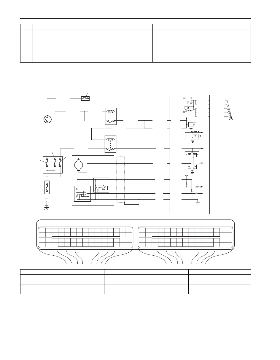
DTC P2101: Throttle Actuator Control Motor Circuit Range / Performance
S5JB0A1104077
Wiring Diagram
17 ABS warning lamp check
1) Connect connectors to all control modules
communicating by CAN.
2) Turn ignition switch ON.
Is ABS warning lamp light up?
Substitute a known-
good ABS hydraulic unit
/ control module
assembly and recheck.
Substitute a known-
good ECM and recheck.
Step
Action
Yes
No
E23
C37
3
4
18
19
5
6
7
10
11
17
20
47
46
49
50
51
21
22
52
16
25
9
24
14
29
55
57
54 53
59
60
58
2
26
27
28
15
30
56
48
32
31
34
35
36
37
40
42
39 38
44
45
43
41
33
1
12
13
23
8
3
4
18
19
5
6
7
10
11
17
20
47
46
49
50
51
21
22
52
16
25
9
24
14
29
55
57
54 53
59
60
58
2
26
27
28
15
30
56
48
32
31
34
35
36
37
40
42
39 38
44
45
43
41
33
1
12
13
23
8
12V
5V
BLU/BLK
BLU/BLK
BLK/RED
1
2
BLK/RED
BLK/RED
BLU
E23-1
E23-60
C37-15
C37-29
C37-48
BLK/ORN
C37-58
BLU/ORN
GRN
BLU/RED
BLU/YEL
BLU/RED
E23-16
E23-50
E23-17
C37-45
C37-44
1-1
1-2
1-3
3
4
5
8
6
7
10
9
E23-29
BLK/YEL
BLK/WHT
WHT/GRN
C37-30 BLK/ORN
BLK/YEL
BLK/YEL
BLK/YEL
BLU/BLK
BLU/BLK
WHT
BLK
RED
GRN
C37-53
C37-54
C37-40
C37-41
I5JB0A110069-01
1. Electric throttle body assembly
3. ECM
8. “IGN” fuse
1-1. Throttle actuator
4. Main relay
9. “IG COIL” fuse
1-2. Throttle position sensor (main)
5. Fuse box No.2
10. Ignition switch
1-3. Throttle position sensor (sub)
6. “THR MOT” fuse
2. Throttle actuator control relay
7. “FI” fuse