Suzuki: Engine K6A-YH6. Manual - part 23


  Index      Suzuki     Suzuki: Engine K6A-YH6 - service repair manual 2008 year


Search            


Content   ..  21  22  23  24   ..


Suzuki: Engine K6A-YH6. Manual - part 23


7-46

REPAIR

7

9.

Apply Three Bond™ 1215 to the lower crankcase 
mating surface.

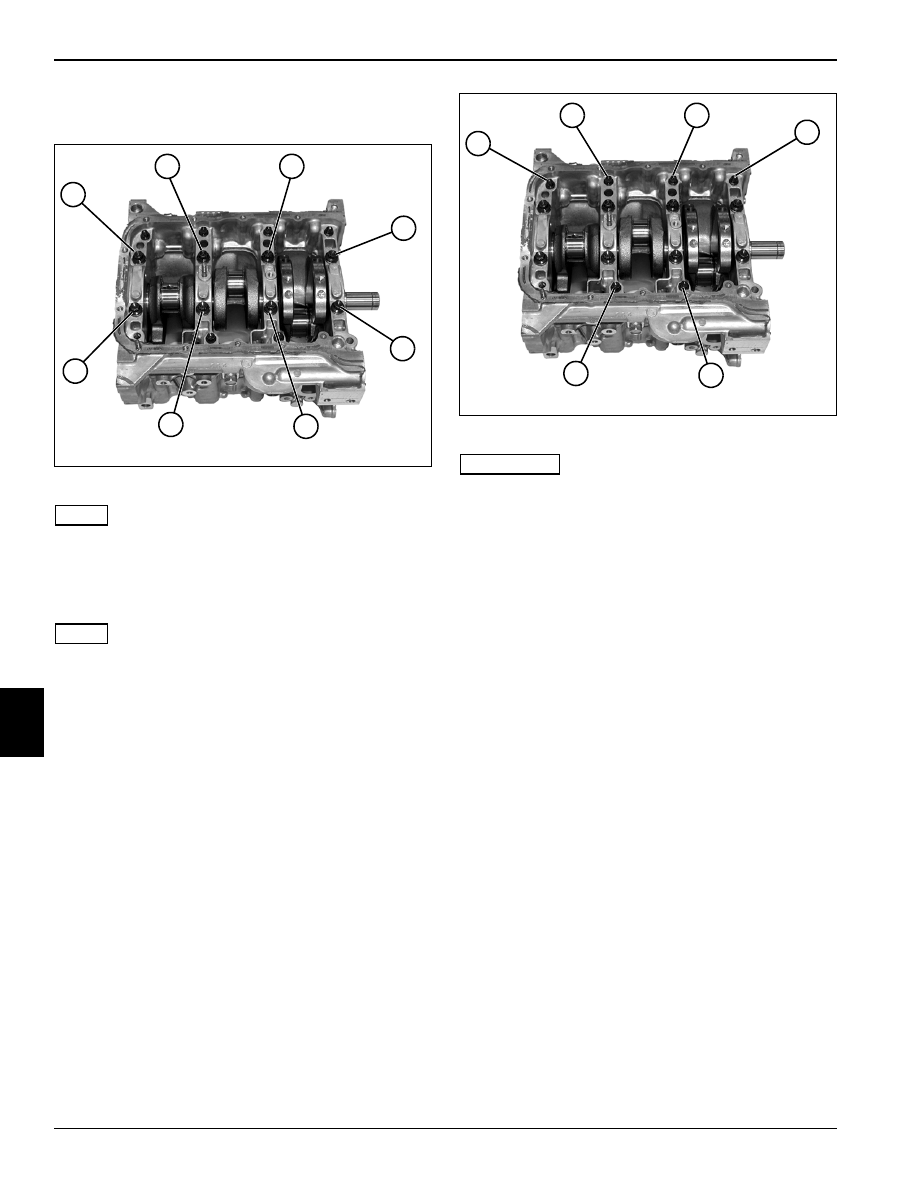
Figure 7-105: Torque Sequence M10 Cap Screws

NOTE

Apply a liberal amount of clean engine oil to lower 
crankcase main bearings and crankshaft main bearing 
journals.

10. Install lower crankcase to cylinder block.

NOTE

Apply engine oil to the threads of M10 cap screws and 
washers and install as shown.

11. Using a 12-point 10 mm socket, tighten eight screws 

and washers sequentially (12 through 19) to 30 lb-ft
(40 N•m).

Loosen all cap screws in the reverse order.

Tighten eight screws and washers sequentially 
(12 through 19) to 30 lb-ft (40 N•m).

Torque cap screws sequentially (12 through 19) to 
final specification.

Lower Crankcase (M10) Cap Screw Torque: 42 lb-ft 
(57 N•m)

Figure 7-106: Torque Sequence M8 Cap Screws

IMPORTANT

The remaining two M8 main bearing cap screws are 
installed with the crankshaft baffle. (See “Crankshaft 
Baffle” on page 7-32.)

12. Using a 12-point 8 mm socket, tighten six screws and 

washers sequentially (20 through 25) to specification.

Lower Crankcase (M8) Cap Screw Torque: 212 lb-in. 
(24 N•m)

TN0755

13

12

14

15

16

17

18

19

TN0755

21

20

22

23

24

25

REPAIR

7-47

7

Figure 7-107

13. Apply Three Bond™ 1215 to cylinder block/lower 

crankcase joints (26).

NOTE

Apply clean engine oil to rear main seal inner diameter 
and crankshaft stub seal surface.

14. Using a bushing, bearing, and seal driver tool, install 

new rear main seal (27).

15. Rotate crankshaft and check for any abnormal 

resistance.

16. Install crankshaft baffle. (See “Crankshaft Baffle” on 

page 7-32.)

17. Install oil pump pickup. (See “Oil Pump Pickup” on 

page 7-31.)

18. Install oil pan. (See “Oil Pan” on page 7-30.)

19. Install cylinder head. (See “Cylinder Head” on 

page 7-24.)

TN0759

26

26

27

8

8-1

Chapter 8

Tools and Materials

Special Tools  . . . . . . . . . . . . . . . . . . . . . . . . . . . . . . . . . . . . . . . . . . . . . . . . . . . . . . . . . . . . . . . . . 8-1

Required Materials . . . . . . . . . . . . . . . . . . . . . . . . . . . . . . . . . . . . . . . . . . . . . . . . . . . . . . . . . . . . . 8-2

8-2

TOOLS AND MATERIALS

8

Special Tools

See Figures 8-1 through 8-9.

The following tools or suitable equivalents must be used 
to perform some procedures within this manual. Always 
use the correct tool for the job.

Figure 8-1: Oil Filter Wrench

Figure 8-2: Oil Pressure Gauge

Figure 8-3: Oil Pressure Gauge Attachment

Figure 8-4: Compression Gauge Set

Figure 8-5: Compression Gauge Hose

Description

Suzuki Part Number

Oil Filter Wrench

09915-47341

Oil Pressure Gauge

09915-77311

Oil Pressure Gauge 
Attachment

09915-78211

Compression Gauge 
Set

09915-64512

Compression Gauge 
Hose

09915-64530

Compression Gauge 
Hose Attachment B

09915-64550

Vacuum Gauge

09915-67311

Tappet Holder

(Jacobsen PN) 4139726

Regulator

09918-18111


Content   ..  21  22  23  24   ..