Peugeot 205. Manual - part 45


  Главная      Peugeot     Peugeot 205 - Service And Repair Manual Haynes


поиск по сайту            


содержание   ..  43  44  45  46   ..


Peugeot 205. Manual - part 45


22 If an earth connection is thought to be
faulty, dismantle the connection, and clean
both the bodyshell and the wire terminal (or
the component earth connection mating
surface) back to bare metal. Be careful to
remove all traces of dirt and corrosion, then
use a knife to trim away any paint, so that a
clean metal-to-metal joint is made. On
reassembly, tighten the joint fasteners
securely; if a wire terminal is being refitted,
use serrated washers between the terminal
and the bodyshell, to ensure a clean and
secure connection. When the connection is
remade, prevent the onset of corrosion in the
future by applying a coat of petroleum jelly or
silicone-based grease, or by spraying on (at
regular intervals) a proprietary ignition sealer,
or a water-dispersant lubricant.

3

Fuses and relays - general
information

Fuses

The fuse board is located above the
glovebox on the left-hand side of the facia.
Blade type fuses are used and symbols by
the fuses denote the circuit protected.
On GTI models an in-line fuse for the fuel
pump is located near the rear of the fuse
board. The fuse board also incorporates a
connector which can be adjusted to supply
the radio with negative or positive current
according to the polarity of the radio fitted. On
later models, additional fuses are located
behind the left-hand side of the radiator, on
the left-hand side of the bulkhead, and near
the horn on 1.9 GTI models.
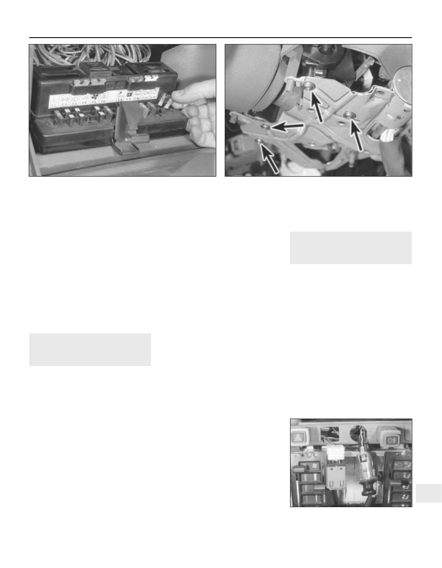
To remove a fuse, first switch off the ignition
then open the glovebox. Depress the spring
clip and lower the fuse board. Pull the fuse out
of its terminals; the wire within the fuse should
be visible; if the fuse is blown the wire will be
broken or melted (see illustration).

Always renew a fuse with one of an
identical rating; never use a fuse with a
different rating from the original or substitute
anything else. Never renew a fuse more than
once without tracing the source of the trouble.
The fuse rating is stamped on top of the fuse;
note that fuses are also colour-coded for easy
recognition.
Persistent blowing of a particular fuse
indicates a fault in the circuit(s) protected.
Where more than one circuit is involved,
switch on one item at a time until the fuse
blows, so showing in which circuit the fault
lies.
Besides a fault in the electrical component
concerned, a blown fuse can also be caused
by a short-circuit in the wiring to the
component. Look for trapped or frayed wires
allowing a live wire to touch vehicle metal, and
for loose or damaged connectors.
The fuse board is retained at the rear by
two plastic ball and socket joints which can
be snapped apart to remove the assembly. 

Relays

A relay is an electrically-operated switch,
which is used for the following reasons:

a) A relay can switch a heavy current

remotely from the circuit in which the
current is flowing, allowing the use of
lighter gauge wiring and switch contacts.

b) A relay can receive more than one control

input, unlike a mechanical switch.

c) A relay can have a timer function - for

example an intermittent wiper delay.

10 If a circuit which includes a relay develops
a fault, remember that the relay itself could be
faulty. Testing is by substitution of a known
good relay. Do not assume that relays which
look similar are necessarily identical for
purposes of substitution.
11 Relays are incorporated in most circuits
and are mounted on the fuse board or within
the engine compartment.

12 Make sure that the ignition is switched off,
then pull the relay from its socket. Push the
new relay firmly in to refit. Refer to the wiring
diagram key for a list of relays.

4

Switches - removal and
refitting

2

Steering column combination
switches

Disconnect the battery negative lead. 
Remove the steering wheel and column
shrouds, with reference to Chapter 10.
Disconnect the wiring harness plug. 
Remove the relevant screws and withdraw
the switch from the column platform (see
illustration)

Refitting is a reversal of removal.

Facia switches (pre-1988
models)

Disconnect the battery negative lead. 
Carefully prise out the switch against the
tension of the plastic retaining tabs (see
illustration)

Disconnect the wiring or multi-plug, noting
the fitted location, and remove the switch. 
Refitting is a reversal of removal.

Body electrical system  12•5

12

4.7 Heated rear window switch and cigar

lighter removed from facia

3.4 Removing a fuse

4.4 Combination switch screws (arrowed)

Facia switches (1988 models
onward)

10 Disconnect the battery negative lead.
11 Open the ashtray.
12 Unclip the bottom of the clock surround
(where fitted) and remove it.
13 Remove the screws from the bottom of
the switch panel, then insert lengths of
welding rod (or similar) into the special holes,
and remove the switch panel surround (see
illustrations)
.
14 The individual switches may now be
removed by inserting two small screwdrivers
in the slots on each side of the switch,
extracting the switch, and disconnecting the
wiring.
15 Refitting is a reversal of removal.

Instrument panel rheostat -
removal and refitting

16 Prise the rheostat from the steering
column lower shroud, and disconnect the
wiring (see illustration)
17 Refitting is a reversal of removal.

Reversing light switch - removal
and refitting

18 Disconnect the wiring and unscrew the
switch from the top or side of the transmission
housing  (see illustration). Remove the
washer.
19 Refitting is a reversal of removal, but
renew the washer if necessary

Courtesy light switch

20 Disconnect the battery negative lead.

21 The switch is secured to the door pillar by
a self-tapping screw. Extract the screw and
withdraw the switch and leads (see
illustration)

22 If the leads are disconnected, tape them
to the pillar to prevent them from slipping
inside the pillar cavity. 
23 It is recommended that the metal contacts
of the switch are smeared with petroleum jelly
as a precaution against corrosion. 
24 Refit by reversing the removal operation.

Glovebox illumination switch

25 Disconnect the battery negative lead. 
26 Open the glovebox then reach up and
release the switch from the inside of the facia
(see illustration)
27 Disconnect the wiring. 
28 Refitting is a reversal of removal.

Ignition switch/steering column
lock

29 Refer to Chapter 10.

Handbrake warning switch

30 Move the front seats fully forward then
remove the screw and lift the cover from the
handbrake lever. 
31 With the handbrake applied, remove the
mounting screw, withdraw the switch and
disconnect the wiring (see illustration)
32 Refitting is a reversal of removal.

Brake stop light switch

33 Disconnect the battery negative lead. 
34 Remove the lower facia panel from the
steering column.
35 Disconnect the two wires (see
illustration)
.

12•6 Body electrical system

4.13a  On later models, remove the switch

panel lower screws . . .

4.13b  Insert lengths of rod into the special

holes . . .

4.13c  . . . and withdraw the switch panel

surround

4.21  Removing a courtesy light switch

4.26  Glovebox illumination switch

4.31  Handbrake warning light switch

(arrowed)

4.16  Instrument illumination rheostat

4.18  Reversing light switch location on the

BH3 transmission

36 Unscrew the locknut nearest the pedal,
and withdraw the switch from the bracket.
37 Refitting is a reversal of removal, but
adjust the locknuts so that the distance
between the end of the switch threaded body
and the pedal (fully released) is 3.5 mm.

5

Instrument panel - removal
and refitting

2

Removal

Pre-1988 models

Disconnect the battery negative lead. 
On non-GTI models, using an Allen key,
unscrew the two upper retaining screws at
each end of the panel surround (see
illustration)

On GTI models, remove the plastic tray
from the top of the panel surround by pushing
it towards the windscreen to release the
securing clips. Unscrew the now-exposed
panel surround securing screw. 
Unscrew the two lower surround retaining
screws located either side of the steering
column shroud (see illustration)

Withdraw the surround from the facia. 
Pull out the instrument panel while
depressing the lower spring supports, then
disconnect the multi-plugs and speedometer
cable (see illustrations)
If necessary, the individual components can
be removed for repair or renewal (see
illustrations)
.

1988 models onward

Disconnect the battery negative lead.
Remove the trapezium-shaped coin
compartment or cover from the top of the
facia by lifting the bottom edge.
10 Pull off the heater control knobs, using
card or thick cloth and pliers on the central
bars.
11 Remove the screws beneath the outer
control knobs, and withdraw the upper front
panel surround.
12 Remove the screws and withdraw the
visor trim from the instrument panel.

Body electrical system  12•7

12

4.35  Brake stop light switch wiring

connector (arrowed)

5.6a  Instrument panel spring support

5.6b  Instrument panel right-hand upper multiplug

5.2  Removing the instrument panel upper . . .

5.4  . . . and lower retaining screws

12•8 Body electrical system

5.7a  Exploded diagram of non-GTI instrument panel

5.7b  Exploded diagram of GTI instrument panel


содержание   ..  43  44  45  46   ..