содержание .. 37 38 39 40 ..
Peugeot 205. Manual - part 39
mounting in a vice and attempting to extend
and retract it. If the resistance is not firm and
even in both directions, or if there are signs of
leakage or damage, the shock absorber must
be renewed.
Refitting
6 Refitting is a reversal of removal, but renew
the self-locking nuts. The nuts must be
tightened when the distance between the
mounting bolt centres is 288.0 mm. The
Peugeot tool 80911 for this operation consists
of a bar and adjustable bolt located beneath
the lifting ramp and hooked on the suspension
tube; however, loading the rear of the car by
trial and error will produce the same result.
11 Rear suspension assembly -
removal and refitting
4
Removal
1 Chock the front wheels then jack up the
rear of the car and support it on axle stands
(see “Jacking and vehicle support”).
2 Remove the handbrake cables, with
reference to Chapter 9.
3 Remove the complete exhaust system, with
reference to Chapter 4D.
4 Disconnect the flexible brake hoses from
the rear suspension assembly, with reference
to Chapter 9.
5 Unscrew the left-hand rear mounting nut,
remove the exhaust bracket then temporarily
refit the nut.
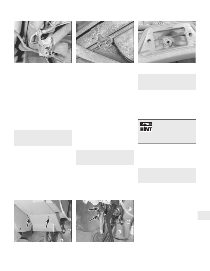
6 Unbolt and remove the front clamp and
bracket (see illustration), but do not unscrew
the seat belt anchorage (where fitted).
7 Adjust the position of the car on the axle
stands so that the rear wheels are just
touching the ground, then place additional
stands or jacks beneath the suspension tube.
8 Working in the luggage compartment
unscrew the front and rear mounting nuts then
carefully withdraw the assembly from under
the car.
Refitting
9 Refitting is a reversal of removal, but tighten
all nuts and bolts to the specified torque.
When tightening the front clamp make sure
that the ring is centred in the seat belt
anchorage bracket. Refer to Chapter 4D and 9
when refitting disturbed exhaust and braking
system components and bleed the brake
hydraulic system on completion.
12 Vehicle ride height - checking
5
Checking of the vehicle ride height requires
the use of Peugeot special tools to accurately
compress the suspension in a suspension
checking bay.
The operation should be entrusted to a
Peugeot dealer, as it not possible to carry out
checking accurately without the use of the
appropriate tools.
13 Steering wheel - removal and
refitting
2
Removal
1 Set the front wheels in the straight-ahead
position.
2 Prise out the centre pad, then use a socket
to unscrew the retaining nut (see illustration).
3 Mark the hub in relation to the inner column
then pull off the steering wheel.
Refitting
4 Refitting is a reversal of removal, but check
that the steering wheel is correctly centred
with the front wheels straight ahead. Tighten
the nut while holding the steering wheel rim.
14 Steering column and lock -
removal and refitting
4
Removal
1 Remove the steering wheel, (Section 13).
2 Remove the lower trim panel from under the
steering column (see illustration).
3 Mark the column lower universal joint in
relation to the intermediate shaft then
unscrew and remove the clamp bolt (see
illustration).
4 Remove the combination switches, as
described in Chapter 12.
5 Disconnect the ignition switch wiring
connectors.
6 Unscrew the mounting nuts and bolts,
disconnect the inner column from the
intermediate shaft, and withdraw the steering
column from the car. Where shear bolts are
fitted they must be drilled to remove the
heads, then unscrewed after removing the
column.
Suspension and steering 10•7
10
10.2 Rear shock absorber bottom
mounting
11.6 Rear suspension cross-tube front
clamp and seat belt anchorage
13.2 Steering wheel retaining nut
14.2 Steering column lower trim panel
screws (arrowed)
14.3 Steering column lower universal joint
and clamp bolt (arrowed)
If the wheel is tight, tap it up
near the centre, using the
palm of your hand, or twist it
from side to side, whilst
pulling upwards to release it from the
shaft splines.