Peugeot 205. Manual - part 7


  Главная      Peugeot     Peugeot 205 - Service And Repair Manual Haynes


поиск по сайту            


содержание   ..  5  6  7  8   ..


Peugeot 205. Manual - part 7


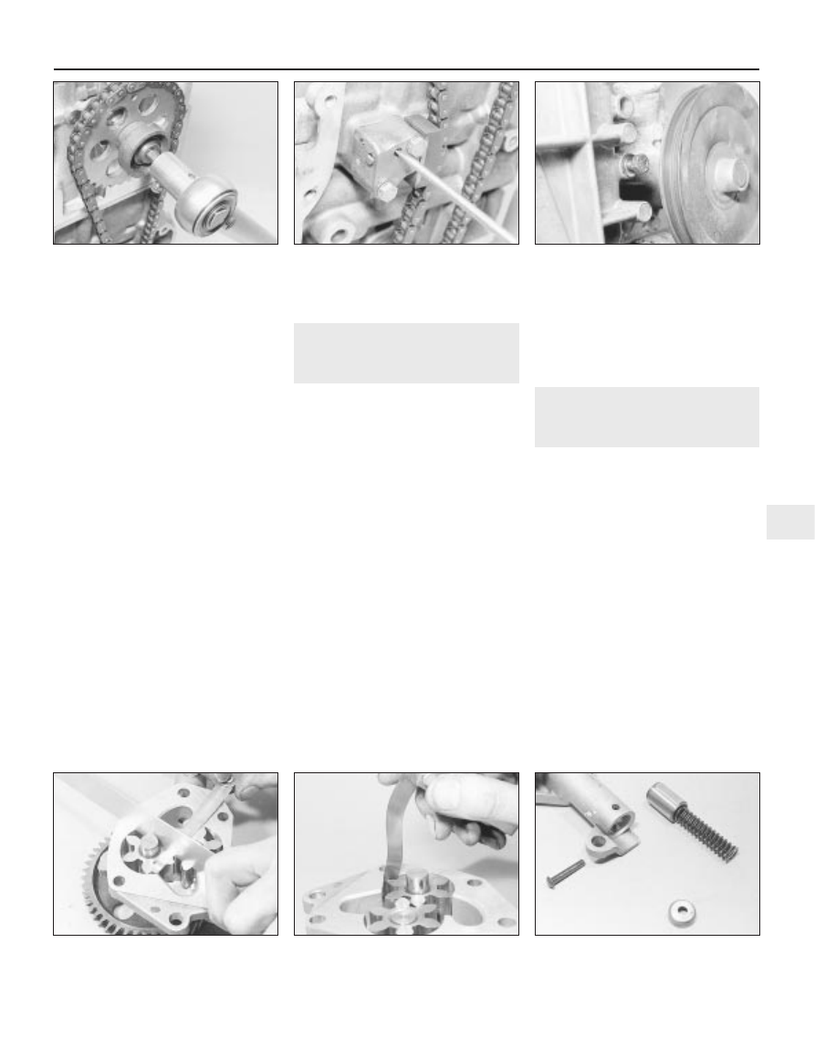
24 Using a very thin screwdriver blade, turn
the lock on the chain tensioner fully clockwise
to release the slipper (see illustration).
25 Check that the locating dowel is in
position and fit the oil pump with spacer plate.
If the pump driven sprocket is hard to turn,
release the pump mounting bolts and turn the
pump slightly on its locating dowel.
Re-tighten the bolts.
26 Fit the oil pump drivegear to the
crankshaft.
27 Bolt on the timing chain cover using a new
gasket. The bolt nearest the coolant pump
pulley must be located in the cover before
offering it up, otherwise the pulley will prevent
the bolt entering its cover hole (see
illustration)
. Do not tighten the cover bolts until
the crankshaft pulley has been pushed into
place to centralise the cover. Fit the coolant
hose safety rod under its cover bolts. This rod
prevents the coolant hose being cut by the rim
of the coolant pump pulley should the hose sag.
28 Fit the fuel pump operating rod and fuel
pump with reference to Chapter 4A, if
necessary. 
29 Tighten the timing chain cover bolts to the
specified torque and then trim the upper ends
of the gasket flush. Fit the rocker cover using
a new gasket. Do not overtighten the securing
bolts. 
30 Tighten the crankshaft pulley nut to the
specified torque, again jamming the flywheel
to prevent the crankshaft rotating.
31 Refit the starter, if removed (Chapter 5A). 
32 Refit and tension the auxiliary drivebelt
(Chapter 1). 

33 Lower the engine, reconnect the
mounting.

5

Oil pump - removal,
inspection and refitting

3

Removal

Carry out the operations described in
Section 4, paragraphs 1 to 10.

Inspection

The oil pump gears are exposed once the
spacer plate is removed.
Side movement of the gear spindles will
indicate wear in the bushes and the pump
should be renewed complete.
Worn or chipped gear teeth must be
rectified by renewal of the gear. 
Check the endfloat of the gears using a
straight-edge and feeler blades (see
illustration)
.
Check the clearance between the tip of the
gear lobes and the oil pump body (see
illustration)

If any of these clearances exceed the
specified limit, renew the pump. 
Remove the retaining pin from the relief
valve housing and withdraw the cup, spring,
guide and piston. Renew any worn
components 

(see illustration).

Check that the locating dowel is in position
and fit the oil pump with spacer plate. If the
pump driven sprocket is hard to turn, release

the pump mounting bolts and turn the pump
slightly on its locating dowel. Re-tighten the
bolts.

Refitting

10 Carry out the operations described in
Section 4, paragraphs 24 to 33.

6

Camshaft and rocker arms -
removal, inspection and
refitting

4

General information

The rocker arm assembly is secured to the
top of the cylinder head by the cylinder head
bolts. Although in theory it is possible to undo
the head bolts and remove the rocker arm
assembly without removing the head, in
practice, this is not recommended. Once the
bolts have been removed, the head gasket will
be disturbed, and the gasket will almost
certainly leak or blow after refitting. For this
reason, removal of the rocker arm assembly
cannot be done without removing the cylinder
head and renewing the head gasket.
The camshaft is slid out of the right-hand
end of the cylinder head, and it therefore
cannot be removed without first removing the
cylinder head, due to a lack of clearance.

Removal

Rocker arm assembly

Remove the cylinder head as described in
Section 7.

XV, XW and XY series engine in-car repair procedures  2A•5

2A

4.23  Tightening the camshaft sprocket

retaining bolt

4.24  Releasing the timing chain tensioner

4.27  Timing cover bolt next to coolant

pump pulley in place prior to fitting cover

5.5  Checking oil pump gear endfloat

5.6  Checking oil pump gear to body

clearance

5.8  Oil pump pressure relief valve

components

To dismantle the rocker arm assembly,
carefully prise off the circlip from the end of
the rocker shaft; retain the rocker pedestal, to
prevent it being sprung off the end of the
shaft. Slide the various components off the
end of the shaft, keeping all components in
their correct fitted order (see illustrations).
Make a note of each component’s correct
fitted position and orientation as it is removed,
to ensure it is fitted correctly on reassembly.
To separate the remaining pedestal and
shaft, first unscrew the rocker cover retaining
stud from the top of the pedestal; this can be
achieved using a stud extractor, or two nuts
locked together. With the stud removed,
unscrew the grub screw from the top of the
pedestal, and withdraw the rocker shaft.

Camshaft

Remove the cylinder head as described in
Section 7.
Undo the retaining bolt, and remove the
camshaft retaining thrust plate from the
cylinder head (see illustration).
Withdraw the camshaft taking care not to
scratch the bearing journals with the edges of
the cam lobes (see illustration).

Inspection

Rocker arm assembly

Examine the rocker arm bearing surfaces
which contact the camshaft lobes for wear
ridges and scoring. Renew any rocker arms
on which these conditions are apparent. If a
rocker arm bearing surface is badly scored,
also examine the corresponding lobe on the
camshaft for wear, as it is likely that both will
be worn. Renew worn components as
necessary. The rocker arm assembly can be
dismantled as described in paragraphs 4
and 5.
10 Inspect the ends of the (valve clearance)
adjusting screws for signs of wear or damage,
and renew as required.
11 If the rocker arm assembly has been

dismantled, examine the rocker arm and shaft
bearing surfaces for wear ridges and scoring.
If there are obvious signs of wear, the relevant
rocker arm(s) and/or the shaft must be
renewed.

Camshaft

12 Examine the camshaft bearing surfaces
and cam lobes for signs of wear ridges and
scoring. Renew the camshaft if any of these
conditions are apparent. Examine the
condition of the bearing surfaces, both on the
camshaft journals and in the cylinder head. If
the head bearing surfaces are worn
excessively, the cylinder head will need to be
renewed. If the necessary measuring
equipment is available, camshaft bearing
journal wear can be checked by direct
measurement, noting that No 1 journal is at
the transmission end of the head.
13 Examine the thrust plate for signs of wear
or scoring, and renew as necessary.

Refitting

Camshaft

14 Ensure that the cylinder head and
camshaft bearing surfaces are clean, then
liberally oil the camshaft bearings and lobes.
Slide the camshaft back into position in the
cylinder head.

15 Locate the thrust plate in position, refit the
plate retaining bolt, tightening it to the
specified torque setting.

Rocker arm assembly

16 If the rocker arm assembly was
dismantled, refit the rocker shaft to the
pedestal, aligning its locating hole with the
pedestal threaded hole. Refit the grub screw,
and tighten it securely. With the grub screw in
position, refit the rocker cover mounting stud
to the pedestal, and tighten it securely. Apply
a smear of clean engine oil to the shaft, then
slide on all removed components, ensuring
each is correctly fitted in its original position.
Once all components are in position on the
shaft, compress the remaining pedestal and
refit the circlip. Ensure that the circlip is
correctly located in its groove on the shaft.
17 Refit the cylinder head and rocker arm
assembly as described in Section 7.

7

Cylinder head - removal and
refitting

4

Note: If the crankshaft is to be rotated after
removal of the cylinder head (for cleaning the
pistons) it will be necessary to use the
Peugeot special tool to hold the camshaft

2A•6 XV, XW and XY series engine in-car repair procedures

6.7  Camshaft retaining thrust plate

6.8  Removing the camshaft

6.4a Prise off the circlip (arrowed) from the end of the 

rocker shaft . . .

6.4b  . . . and slide the components off the shaft

sprocket, or fabricate a suitable alternative. If it
will not be necessary to rotate the crankshaft,
the home-made tool described in the text will
suffice.

Removal

Disconnect and remove the battery, as
described in Chapter 5A.
Remove the air cleaner, complete with
mounting brackets, hot air hose and inlet
hose, with reference to Chapter 4A. Also
remove the inlet cowl.
Drain the cooling system, as described in
Chapter 1.
Remove the engine oil filler/crankcase
ventilation cap and disconnect the hoses from
the inlet cowl and carburettor.
Chock the rear wheels then jack up the
front of the car and support it on axle stands
(see “Jacking and vehicle support”).
Disconnect the gearchange selector and

engagement rods with reference to Chapter 7A.
Unscrew the engagement rod nut. Make sure
that the gears are in neutral.
Unscrew the bolt and nuts, and disconnect
the exhaust downpipe from the exhaust
manifold.
Loosen the left-hand engine mounting nuts
beneath the battery tray so that the mounting
is lowered by approximately 4.0 mm.
Disconnect the heater hoses from the
bulkhead, water pump and cylinder head
outlet. 
10 Remove the fuel pump, as described in
Chapter 4A. 
11 Disconnect the top hose from the
thermostat housing. 
12 Disconnect the temperature sender
wiring. 
13 Remove the distributor, as described in
Chapter 5B. 
14 Disconnect the spark plug HT leads and
remove them from the rocker cover. 
15 Disconnect the throttle and choke cables,
as described in Chapter 4A. 
16 Disconnect the brake servo vacuum hose
from the inlet manifold (if applicable) and
place to one side.
17 Unscrew and remove the two bolts
securing the right-hand rear engine mounting
to the subframe (see illustration).
18 Using a suitable long bar inserted through
the right-hand rear engine mounting bracket,

lever up the rear of the engine as far as
possible, without damaging the radiator, and
support with a block of wood (see
illustration)
. If necessary, loosen the left-hand
engine mounting to gain extra height. Make
sure that the right-hand front mounting is not
damaged by excessive twisting.
19 Unbolt the rocker cover and remove the
gasket.
20 Turn the engine on the crankshaft pulley
nut until the key slot in the camshaft is facing
upwards, then remove the ignition timing
aperture cover and turn the engine as
necessary until the mark on the flywheel is
aligned with the TDC mark on the timing
plate (refer to Chapter 5B if necessary).
Pistons No 2 and 3 will be at TDC.
21 Extract the fuel pump plunger from the
timing cover (see illustration).
22 Unbolt the access plate from the top of
the timing cover.
23 Unscrew and remove the camshaft
sprocket retaining bolt from the end of the
camshaft using an Allen key (retain the
sprocket with a suitable bar) (see
illustration)
.
24 Loosen the four bolts securing the timing
cover to the cylinder head (see illustration).
25 Progressively unscrew the cylinder head
bolts in the order shown (see illustration),
and recover the nuts from their channels in
the crankcase. 

XV, XW and XY series engine in-car repair procedures  2A•7

2A

7.17  Right-hand rear engine mounting

bolts

7.18  Lever up the engine and support it on

a wooden block

7.21  Removing the fuel pump plunger

7.23  Unscrew and remove the camshaft

sprocket bolt

7.24  Loosen the bolts securing the timing

cover to the cylinder head

7.25  Sequence for tightening or loosening the cylinder head bolts

26 Remove the head bolts and lift off the
rocker shaft assembly (see illustration). It
may be necessary to leave one or two bolts in
the assembly if they foul the bulkhead due to
insufficient engine height.
27 Loosen the camshaft thrust plate bolt, pull
out the plate and temporarily retighten the
bolt (see illustration).
28 The camshaft sprocket must now be
supported in its normal position while the

cylinder head is removed. If it is allowed to
drop it will not be possible to lift it again
without releasing the timing chain tensioner
which will necessitate removal of the timing
cover. Peugeot dealers use a special mandrel,
tool number 70132, but as this is unlikely to
be available to the home mechanic it is
suggested that a plate and bolt are used,
together with the access plate (see Tool Tip).
29 Slide the camshaft from the fuel pump
eccentric and camshaft sprocket and let it
rest in the cylinder head (see illustration).
30 Before removing the cylinder head the
following must be noted. The cylinder head is
positioned during assembly by means of two
dowels. When removing the cylinder head it is
most important not to lift it directly from the
cylinder block; it must be twisted slightly. This
action prevents the cylinder liners from
sticking to the cylinder head face and being
lifted with it, thus breaking their bottom seals.
Before the cylinder head can be twisted, the
dowel at the flywheel end must be tapped
down flush with the top of the cylinder block,
using a drift (see illustration).

31 Remove the four timing cover-to-cylinder
head bolts then move the flywheel end of the
cylinder head sideways slightly to release the
gasket.
32 Lift the cylinder head from the block and
remove the gasket without disturbing the
liners. Do not turn the engine over as this also
will break the liner bottom seals. If further
work is to be carried out on the engine, such
as cleaning the tops of the cylinder liners, they
should be clamped in position using two
cylinder head bolts, metal tubing, and large
washers (see illustration).

Preparation for refitting

Note: As mentioned at the beginning of this
Section, the camshaft sprocket must be
supported in such a way that it will be allowed
to rotate as the crankshaft is turned to clean
the pistons. The Peugeot special tool locates
through the sprocket retaining bolt hole and is
bolted to the front of the timing cover. If this
tool cannot be obtained, a suitable alternative
can be easily fabricated.
33 With the camshaft sprocket supported so
as to allow rotation, commence the cleaning
operation as follows.
34 The mating faces of the cylinder head and
cylinder block/crankcase must be perfectly
clean before refitting the head. Use a hard

2A•8 XV, XW and XY series engine in-car repair procedures

7.29  Slide the camshaft from the fuel

pump eccentric (arrowed)

7.30  Driving the cylinder head dowel down

flush with the block face

7.26  Removing the rocker shaft assembly

7.27  Loosening the camshaft thrust plate bolt

In the absence of the Peugeot tool, a
nut and bolt used together with the
access plate can be used as shown to
prevent the camshaft sprocket from
dropping.

7.32  Using washers, tubing and the cylinder

head bolts to clamp the liners in position


содержание   ..  5  6  7  8   ..