Opel Frontera UE. Manual - part 994


  Index      Opel     Opel Frontera UE - service repair manual 1999-2001 year


Search            copyright infringement  


Content   ..  992  993  994  995   ..


Opel Frontera UE. Manual - part 994


6J–2

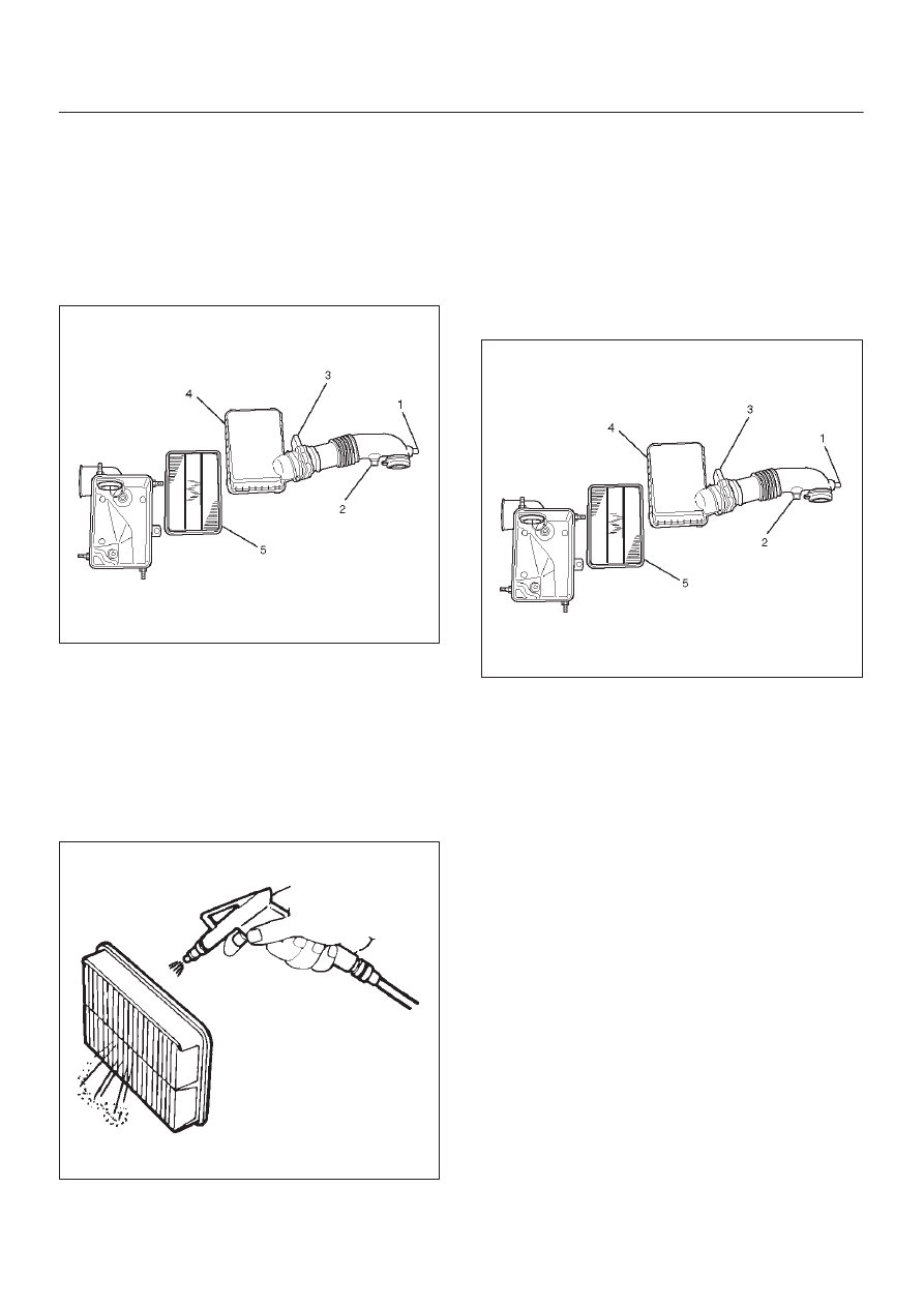
INDUCTION (6VD1 3.2L)

Air Cleaner Element

Removal

1. Remove positive ventilation hose connector(1).
2. Remove intake air temperature sensor(2).
3. Remove air flow sensor(3).
4. Remove air cleaner duct assembly(4).
5. Remove air cleaner element(5).

130RW003

Inspection

Check the air cleaner filter for damage or dust clogging.
Replace if it is damaged, or clean if it is clogged.

Cleaning Method

Tap the air cleaner filter gently so as not to damage the
paper filter, or clean the element by blowing with
compressed air of about 490 kPa (71 psi) from the clean
side if it is extremely dirty.

130RW002

Installation

1. Install air cleaner element(5).
2. Attach the mass air cleaner duct cover to the body

completely, then clamp it with the clip(4).

3. Install air flow sensor(3).
4. Install air temprature sensor(2).
5. Install positive crankcase ventilation hose

connector(1).

130RW003

7A–1

AUTOMATIC TRANSMISSION (4L30–E)

FRONTERA

TRANSMISSION

CONTENTS

Automatic Transmission (4L30–E)

7A

. . . . . . . . . 

Transmission Control System (4L30–E)

7A1

. . . . 

Manual Transmission

7B

. . . . . . . . . . . . . . . . . . . . 

Clutch

7C

. . . . . . . . . . . . . . . . . . . . . . . . . . . . . . . . . 

AUTOMATIC TRANSMISSION (4L30–E)

CONTENTS

Service Precaution

7A–2

. . . . . . . . . . . . . . . . . . . . . . 

Construction

7A–3

. . . . . . . . . . . . . . . . . . . . . . . . . . . . 

Range Reference Chart

7A–4

. . . . . . . . . . . . . . . . . . 

Normal Operation of 2000 4L30–E
 Transmission

7A–5

. . . . . . . . . . . . . . . . . . . . . . . . . . . 

Diagnosis

7A–5

. . . . . . . . . . . . . . . . . . . . . . . . . . . . . . 

Driver Information

7A–5

. . . . . . . . . . . . . . . . . . . . . . . 

General Diagnosis Procedure

7A–8

. . . . . . . . . . . . . 

Preliminary Inspection Chart

7A–9

. . . . . . . . . . . . . . 

Checking Transmission Fluid Level and
 Condition

7A–10

. . . . . . . . . . . . . . . . . . . . . . . . . . . . . . 

Test Driving

7A–11

. . . . . . . . . . . . . . . . . . . . . . . . . . . . . 

Mechanical / Hydraulic Diagnosis Check
 Trans Indicator Chart

7A–12

. . . . . . . . . . . . . . . . . . . . 

Mechanical / Hydraulic Diagnosis Symptoms
 Index

7A–13

. . . . . . . . . . . . . . . . . . . . . . . . . . . . . . . . . . 

Stall Test

7A–22

. . . . . . . . . . . . . . . . . . . . . . . . . . . . . . . 

Line Pressure Test

7A–23

. . . . . . . . . . . . . . . . . . . . . . 

Shift Speed Chart

7A–24

. . . . . . . . . . . . . . . . . . . . . . . 

Lockup Speed Chart

7A–25

. . . . . . . . . . . . . . . . . . . . . 

Changing Transmission Fluid

7A–26

. . . . . . . . . . . . . 

Selector Lever

7A–26

. . . . . . . . . . . . . . . . . . . . . . . . . . 

Inspection

7A–26

. . . . . . . . . . . . . . . . . . . . . . . . . . . . 

Removal

7A–27

. . . . . . . . . . . . . . . . . . . . . . . . . . . . . 

Installation

7A–28

. . . . . . . . . . . . . . . . . . . . . . . . . . . . 

Select Cable

7A–28

. . . . . . . . . . . . . . . . . . . . . . . . . . . . 

Removal

7A–28

. . . . . . . . . . . . . . . . . . . . . . . . . . . . . 

Installation

7A–30

. . . . . . . . . . . . . . . . . . . . . . . . . . . . 

Shift Lock Cable

7A–32

. . . . . . . . . . . . . . . . . . . . . . . . 

Removal

7A–32

. . . . . . . . . . . . . . . . . . . . . . . . . . . . . 

Installation

7A–33

. . . . . . . . . . . . . . . . . . . . . . . . . . . . 

Mode Switch

7A–34

. . . . . . . . . . . . . . . . . . . . . . . . . . . . 

Removal

7A–34

. . . . . . . . . . . . . . . . . . . . . . . . . . . . . 

Installation

7A–34

. . . . . . . . . . . . . . . . . . . . . . . . . . . . 

Transmission (With Transfer Case)

7A–36

. . . . . . . . 

Transmission and Associated Parts

7A–36

. . . . . . 

Removal

7A–37

. . . . . . . . . . . . . . . . . . . . . . . . . . . . . 

Installation

7A–41

. . . . . . . . . . . . . . . . . . . . . . . . . . . . 

Solenoid (Main Case Valve Body)

7A–45

. . . . . . . . . 

Removal

7A–45

. . . . . . . . . . . . . . . . . . . . . . . . . . . . . 

Installation

7A–45

. . . . . . . . . . . . . . . . . . . . . . . . . . . . 

Solenoid (Adapter Case Valve Body)

7A–46

. . . . . . . 

Removal

7A–46

. . . . . . . . . . . . . . . . . . . . . . . . . . . . . 

Installation

7A–46

. . . . . . . . . . . . . . . . . . . . . . . . . . . . 

Valve Body Assembly (Main Case)

7A–47

. . . . . . . . 

Removal

7A–47

. . . . . . . . . . . . . . . . . . . . . . . . . . . . . 

Installation

7A–47

. . . . . . . . . . . . . . . . . . . . . . . . . . . . 

Valve Body Assembly (Adapter Case)

7A–48

. . . . . . 

Removal

7A–48

. . . . . . . . . . . . . . . . . . . . . . . . . . . . . 

Installation

7A–48

. . . . . . . . . . . . . . . . . . . . . . . . . . . . 

Powertrain Control Module (PCM)

7A–49

. . . . . . . . . 

Removal

7A–49

. . . . . . . . . . . . . . . . . . . . . . . . . . . . . 

Installation

7A–49

. . . . . . . . . . . . . . . . . . . . . . . . . . . . 

Speed Sensor (Extension Housing)

7A–50

. . . . . . . . 

Removal

7A–50

. . . . . . . . . . . . . . . . . . . . . . . . . . . . . 

Installation

7A–50

. . . . . . . . . . . . . . . . . . . . . . . . . . . . 

Transmission Oil Temperature Sensor
 (Adapter Case)

7A–51

. . . . . . . . . . . . . . . . . . . . . . . . . 

Removal

7A–51

. . . . . . . . . . . . . . . . . . . . . . . . . . . . . 

Installation

7A–51

. . . . . . . . . . . . . . . . . . . . . . . . . . . . 

Front Oil Seal (Converter Housing)

7A–52

. . . . . . . . 

Removal

7A–52

. . . . . . . . . . . . . . . . . . . . . . . . . . . . . 

Installation

7A–52

. . . . . . . . . . . . . . . . . . . . . . . . . . . . 

Rear Oil Seal (Extension Housing)

7A–52

. . . . . . . . . 

Removal

7A–52

. . . . . . . . . . . . . . . . . . . . . . . . . . . . . 

Installation

7A–52

. . . . . . . . . . . . . . . . . . . . . . . . . . . . 

Transmission (4L30–E)

7A–53

. . . . . . . . . . . . . . . . . . 

Disassembly

7A–53

. . . . . . . . . . . . . . . . . . . . . . . . . . 

Reassembly

7A–57

. . . . . . . . . . . . . . . . . . . . . . . . . . 

Converter Housing and Oil Pump Assembly

7A–67

Disassembled View

7A–67

. . . . . . . . . . . . . . . . . . . . 

Disassembly

7A–67

. . . . . . . . . . . . . . . . . . . . . . . . . . 

Inspection and Repair

7A–67

. . . . . . . . . . . . . . . . . . 

Reassembly

7A–67

. . . . . . . . . . . . . . . . . . . . . . . . . . 

Oil Pump

7A–68

. . . . . . . . . . . . . . . . . . . . . . . . . . . . . . . 

SECTION

7A–2

AUTOMATIC TRANSMISSION (4L30–E)

Disassembled View

7A–68

. . . . . . . . . . . . . . . . . . . . 

Disassembly

7A–68

. . . . . . . . . . . . . . . . . . . . . . . . . . 

Inspection and Repair

7A–68

. . . . . . . . . . . . . . . . . . 

Reassembly

7A–68

. . . . . . . . . . . . . . . . . . . . . . . . . . 

Main Case Valve Body

7A–69

. . . . . . . . . . . . . . . . . . . 

Disassembled View

7A–69

. . . . . . . . . . . . . . . . . . . . 

Disassembly

7A–70

. . . . . . . . . . . . . . . . . . . . . . . . . . 

Inspection and Repair

7A–70

. . . . . . . . . . . . . . . . . . 

Reassembly

7A–70

. . . . . . . . . . . . . . . . . . . . . . . . . . 

Adapter Case Valve Body

7A–71

. . . . . . . . . . . . . . . . 

Disassembled View

7A–71

. . . . . . . . . . . . . . . . . . . . 

Disassembly

7A–71

. . . . . . . . . . . . . . . . . . . . . . . . . . 

Inspection and Repair

7A–71

. . . . . . . . . . . . . . . . . . 

Reassembly

7A–71

. . . . . . . . . . . . . . . . . . . . . . . . . . 

Third Clutch and Sprag Unit

7A–72

. . . . . . . . . . . . . . 

Disassembled View

7A–72

. . . . . . . . . . . . . . . . . . . . 

Disassembly

7A–72

. . . . . . . . . . . . . . . . . . . . . . . . . . 

Inspection and Repair

7A–73

. . . . . . . . . . . . . . . . . . 

Reassembly

7A–73

. . . . . . . . . . . . . . . . . . . . . . . . . . 

Third Clutch

7A–73

. . . . . . . . . . . . . . . . . . . . . . . . . . . . 

Disassembled View

7A–73

. . . . . . . . . . . . . . . . . . . . 

Disassemble

7A–74

. . . . . . . . . . . . . . . . . . . . . . . . . . 

Inspection and Repair

7A–74

. . . . . . . . . . . . . . . . . . 

Reassembly

7A–74

. . . . . . . . . . . . . . . . . . . . . . . . . . 

Sprag Unit

7A–75

. . . . . . . . . . . . . . . . . . . . . . . . . . . . . . 

Disassembled View

7A–75

. . . . . . . . . . . . . . . . . . . . 

Disassembly

7A–75

. . . . . . . . . . . . . . . . . . . . . . . . . . 

Inspection and Repair

7A–75

. . . . . . . . . . . . . . . . . . 

Reassembly

7A–75

. . . . . . . . . . . . . . . . . . . . . . . . . . 

Second Clutch

7A–76

. . . . . . . . . . . . . . . . . . . . . . . . . . 

Disassembled View

7A–76

. . . . . . . . . . . . . . . . . . . . 

Disassembly

7A–76

. . . . . . . . . . . . . . . . . . . . . . . . . . 

Inspection and Repair

7A–77

. . . . . . . . . . . . . . . . . . 

Reassembly

7A–77

. . . . . . . . . . . . . . . . . . . . . . . . . . 

3–4 Accumulator Piston

7A–78

. . . . . . . . . . . . . . . . . . 

Disassembled View

7A–78

. . . . . . . . . . . . . . . . . . . . 

Disassembly

7A–78

. . . . . . . . . . . . . . . . . . . . . . . . . . 

Inspection and Repair

7A–79

. . . . . . . . . . . . . . . . . . 

Reassembly

7A–79

. . . . . . . . . . . . . . . . . . . . . . . . . . 

Reverse Clutch Piston and Center Support

7A–80

Disassembled View

7A–80

. . . . . . . . . . . . . . . . . . . . 

Disassembly

7A–81

. . . . . . . . . . . . . . . . . . . . . . . . . . 

Inspection and Repair

7A–81

. . . . . . . . . . . . . . . . . . 

Reassembly

7A–81

. . . . . . . . . . . . . . . . . . . . . . . . . . 

Overrun Clutch and Turbine Shaft

7A–82

. . . . . . . . . 

Disassembled View

7A–82

. . . . . . . . . . . . . . . . . . . . 

Disassembly

7A–83

. . . . . . . . . . . . . . . . . . . . . . . . . . 

Inspection and Repair

7A–83

. . . . . . . . . . . . . . . . . . 

Reassembly

7A–83

. . . . . . . . . . . . . . . . . . . . . . . . . . 

Main Data and Specification

7A–85

. . . . . . . . . . . . . . 

Special Tools

7A–89

. . . . . . . . . . . . . . . . . . . . . . . . . . . 

4L30–E Parts List

7A–92

. . . . . . . . . . . . . . . . . . . . . . . 

Service Precaution

WARNING: IF SO EQUIPPED WITH A
SUPPLEMENTAL RESTRAINT SYSTEM (SRS),
REFER TO THE SRS COMPONENT AND WIRING
LOCATION VIEW IN ORDER TO DETERMINE
WHETHER YOU ARE PERFORMING SERVICE ON OR
NEAR THE SRS COMPONENTS OR THE SRS
WIRING. WHEN YOU ARE PERFORMING SERVICE
ON OR NEAR THE SRS COMPONENTS OR THE SRS
WIRING, REFER TO THE SRS SERVICE
INFORMATION. FAILURE TO FOLLOW WARNINGS
COULD RESULT IN POSSIBLE AIR BAG
DEPLOYMENT, PERSONAL INJURY, OR
OTHERWISE UNNEEDED SRS SYSTEM REPAIRS.

CAUTION: Always use the correct fastener in the
proper location. When you replace a fastener, use
ONLY the exact part number for that application.
ISUZU will call out those fasteners that require a
replacement after removal. ISUZU will also call out
the fasteners that require thread lockers or thread
sealant. UNLESS OTHERWISE SPECIFIED, do not
use supplemental coatings (Paints, greases, or other
corrosion inhibitors) on threaded fasteners or
fastener joint interfaces. Generally, such coatings
adversely affect the fastener torque and the joint
clamping force, and may damage the fastener. When
you install fasteners, use the correct tightening
sequence and specifications. Following these
instructions can help you avoid damage to parts and
systems.

7A–3

AUTOMATIC TRANSMISSION (4L30–E)

Construction

A07RS001

Legend

(1) Torque Converter Clutch (TCC)
(2) Fourth Clutch (C4)
(3) Overrun Clutch (OC)
(4) Overdrive Unit
(5) Reverse Clutch (RC)
(6) Second Clutch (C2)

(7) Third Clutch (C3)
(8) Ravigneaux Planetary Gear Set
(9) Brake Band (B)

(10) Overdrive Free Wheel (One Way Clutch)

(OFW)

(11) Principle Sprag Assembly (One Way Clutch)

(PFW)


Content   ..  992  993  994  995   ..