Opel Frontera UE. Manual - part 852


  Index      Opel     Opel Frontera UE - service repair manual 1999-2001 year


Search            copyright infringement  


Content   ..  850  851  852  853   ..


Opel Frontera UE. Manual - part 852


6E1–291

X22SE 2.2L ENGINE DRIVEABILITY AND EMISSION

6. Connect electrical connector to each fuel injector.

014RX036

7. Connect the fuel supply line securely. Do not over

tighten.

8. Connect the fuel return line securely. Do not over

tighten.

9. Connect the negative battery cable.

10. Crank the engine until it start. Cranking the engine

may take longer than usual due to trapped air in the
fuel system. Check for leak. If fuel leak is observed,
stop engine immediately. Before correct fuel leak, be
sure to depressurize system again.

014RX035

Fuel Tank

Removal Procedure

1. Disconnect the negative battery cable.
2. Remove fuel filer cap.

3. Drain the fuel from fuel filler neck.
4. Disconnect the fuel filler hose at fuel tank.
5. Disconnect the air breather hose at the fuel tank.
6. Disconnect the evaporator hose at the fuel tank.
7. Hold entire fuel tank at the bottom with stands.
8. Disconnect fuel supply lines and fuel return line at

near the fuel filter inside of body frame.
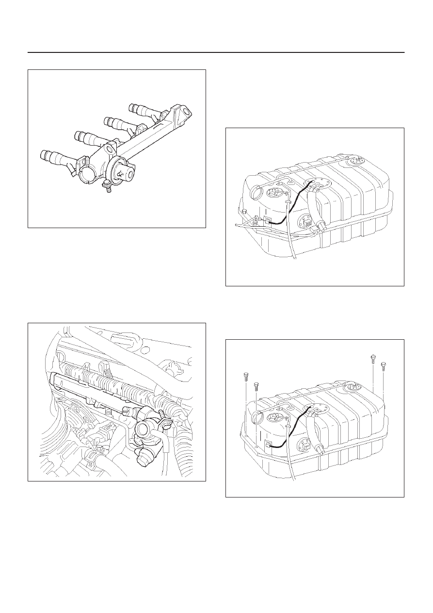
041RX005

9. Remove four bolts (two in front and two in rear)

holding fuel tank to the frame.

10. Lower tank assembly from the vehicle a little to make

access space on top.

11. Disconnect  two electrical connectors at fuel pump.

041RX006

12. Remove fuel tank assembly from the vehicle.
13. Remove four nuts retaining tank under guard to the

tank.

6E1–292

X22SE 2.2L ENGINE DRIVEABILITY AND EMISSION

14. Remove the tank from the guard.

041RX002

Installation Procedure

1. Secure fuel tank into under guard with four retaining

bolts, if necessary.

2. Place the fuel tank assembly onto stands.
3. Lift the fuel tank assembly near the position.
4. Connect two electrical connectors at fuel pump.
5. Lift the fuel pump to its position and secure it with four

mounting bolts. Make sure that all hoses and fuel
lines are out of way between the fuel tank and the fuel
tank bracket. Tighten the fuel tank retaining bolts to
36 Nm (27 lb ft).

041RX007

6. Connect fuel supply and return lines.

7. Connect the fuel filler hose, the air breather hose and

EVAP hose onto fuel tank and secure them with
clamps.

041RX006

8. Pour fuel into fuel tank.
9. Install fuel filler cap securely.

10. Connect the battery negative cable.

041RX005

Throttle body (TB)

Removal Procedure

1. Disconnect the negative battery cable.
2. Drain the cooling system. Refer to Cooling System.
3. Remove the air intake duct. Refer to Air Intake Duct

Removal Procedure. 

4. Remove the accelerator cable from throttle. Refer to

Accelerator Cable Assembly Removal Procedure. 

6E1–293

X22SE 2.2L ENGINE DRIVEABILITY AND EMISSION

5. Disconnect the electrical connectors from the throttle

position sensor and the idle air control valve solenoid.

6. Disconnect all vacuum hoses below air horn.
7. Disconnect coolant lines.

014RX025

8. Remove the mounting bolts retaining the throttle body

the intake manifold.

9. Lift up the throttle body from the intake manifolds.

014RX040

10. Remove the gaskets from the intake manifolds.

11. Remove the IAC. Refer to Idle Air Control Valve

Solenoid Removal Procedure. 

12. Remove TPS. Refer to Throttle Position Sensor

Removal Procedure. 

Inspection Procedure

NOTE: Do not use solvent of any type when you clean the
gasket surfaces on the intake manifold and the throttle
body assembly. The gasket surface and the throttle body
assembly may be damaged as results.

1. If the throttle body gasket needs to be released,

remove any gasket material that may be stuck to the
mating surfaces of the manifold.

2. Do not leave any scratches in the aluminum casting.

014RX041

Installation Procedure

1. Install IAC valve onto the throttle body. Refer to Idle

Air Control Valve Solenoid Installation Procedure. 

2. Install TPS onto the throttle body if necessary. Refer

to TPS Installation Procedure.

3. Place the gasket then the throttle body on the

manifold.

4. Install four mounting bolt. Tighten the throttle body

mounting bolt to 13.5 Nm (10 lb ft).

014RX041

5. Connect coolant line and secure them with clamps.
6. Connect all vacuum hoses and secure them with

clamps if necessary.

7. Install accelerator control cable bracket onto the

throttle body.

6E1–294

X22SE 2.2L ENGINE DRIVEABILITY AND EMISSION

8. Connect accelerator control cable to throttle plate.

014RX025

9. Connect electrical connector at IAC valve and TPS.

10. Install the air intake duct. Refer to Air Intake Duct

Installation Procedure. 

11. Fill the cooling system with required coolant. Refer to

Engine Cooling System.

12. Connect the negative battery cable.

101RX002

ELECTRONIC IGNITION 

SYSTEM  Ignition Control 

Module (ICM)

Removal Procedure

1. Disconnect the negative battery cable.
2. Disconnect the electrical connector from the ignition

control module.

3. Remove the two attaching screws.
4. Remove the ignition control module from the engine

block.

Installation Procedure

1. Fasten the module to the engine block with two

screws.

2. Reconnect the electrical connector.
3. Reconnect the negative battery terminal.

041RX042


Content   ..  850  851  852  853   ..