Opel Frontera UE. Manual - part 492


  Index      Opel     Opel Frontera UE - service repair manual 1999-2001 year


Search            


Content   ..  490  491  492  493   ..


Opel Frontera UE. Manual - part 492


8D–108

WIRING SYSTEM

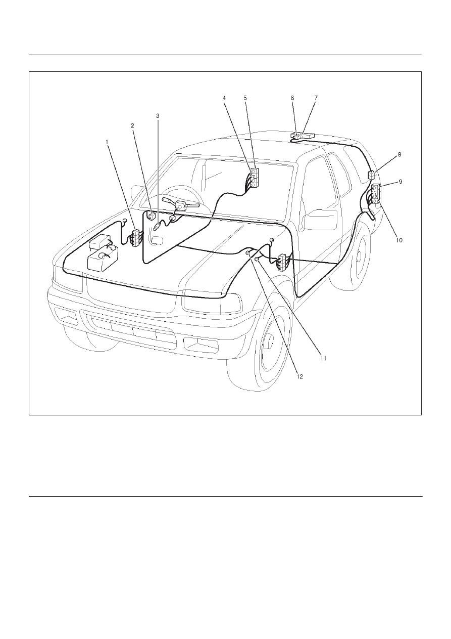
Parts Location (4Door Model)

D08RX203

Legend

(1) H–19
(2) Relay & Fuse Box
(3) I–18
(4) B–9
(5) Stoplight – RH
(6) H–21

(7) G–10, G–11
(8) High Mounted Stoplight
(9) Stoplight – LH

(10) B–13

(11) B–8

(12) B–6

8D–109

WIRING SYSTEM

Diagnosis

Both Stoplights Inoperative

Step

Action

Value(s)

Yes

No

1

Is the fuse C–6 normal?

Go to Step 2

Replace the

fuse

2

Dieconnect the stoplight switch connector I–18.

Is there continuity between connector I–18 terminal 1
and 4 with the brake pedal depressed?

Go to Step 3

Replace or

replace the

switch

3

Is the battery voltage applied between harness side
connector I–18 terminal 1 and the ground?

Approx. 12V

Go to Step 5

Go to Step 4

4

Repair an open circuit between the fuse C–6 and
connector I–18 terminal 1.

Is the action complete?

Verify repair

5

Repair an open circuit between stoplight switch and the
stoplight.

Is the action complete?

Verify repair

Stoplight On The Left (or Right) Side Inoperative

Step

Action

Value(s)

Yes

No

1

1. Disconnect the stoplight connector B–9 or B–13.
2. Depress the brake pedal.

Is the battery voltage applied between stoplight
harness side connector terminal 2 and the ground?

Approc. 12V

Go to Step 2

Go to Step 3

2

Repair an open circuit between the stoplight and the
ground.

Is the action complete?

Verify repair

3

Repair an open circuit between the stoplight switch and
the stoplight.

Is the action complete?

Verify repair

8D–110

WIRING SYSTEM

High Mounted Stoplight Inoperative

Step

Action

Value(s)

Yes

No

1

Depress the brake pedal.

Do the stoplight come on?

Go to Step 3

Go to Step 2

2

Refer to the diagnosis procedure for “Both Stoplights
inoperative” in this section.

Is the action complete?

Verify repair

3

Is B–6 grounded securely?

Go to Step 4

 Ground it

securely

4

1. Disconnect the high mounted stoplight connector.
2. Depress the brake pedal.

Is the battery voltage applied between harness side
connector G–11 terminal 1 or connector G–4 terminal 2
and the ground?

Appprox. 12V

Go to Step 6

Go to Step 5

5

Repair an open circuit between connector H–19
terminal 10 and the high mounted stoplight.

Is the action complete?

Go to Step 4

6

Is there continuity between high mounted stoplight side
connector terminals?

Go to Step 7

Repair or

replace the

light

7

Repair an open circuit between the high mounted
stoplight and the ground B–6.

Is the action complete?

Verify repair

8D–111

WIRING SYSTEM

Backup Light

General Description

The circuit consists of backup light switch (M/T), mode
switch (A/T) and backup light.
When shift lever is set to “R” position, backup light switch
(M/T) or mode switch (A/T) is activated to illuminate
backup light.


Content   ..  490  491  492  493   ..