Opel Frontera UE. Manual - part 377


  Index      Opel     Opel Frontera UE - service repair manual 1999-2001 year


Search            


Content   ..  375  376  377  378   ..


Opel Frontera UE. Manual - part 377


6E2–314

6VD1 3.2L ENGINE DRIVEABILITY AND EMISSIONS

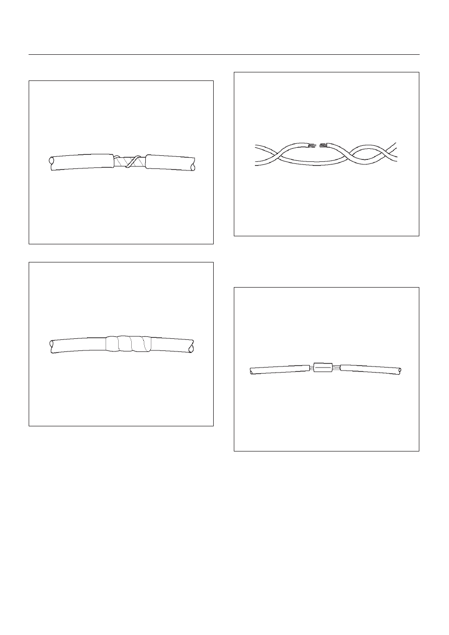
3. Wrap the splice with mylar and with the drain

(uninsulated) wire.

049

4. Tape over the whole bundle to secure.

050

Twisted Leads

Removal Procedure

1. Locate the damaged wire.

2. Remove the insulation as required.

051

Installation Procedure

1. Use splice clips and rosin core solder in order to splice

the two wires together.

052

6E2–315

6VD1 3.2L ENGINE DRIVEABILITY AND EMISSIONS

2. Cover the splice with tape in order to insulate it from

the other wires.

053

3. Twist the wires as they were before starting this

procedure.

054

4. Tape the wires with electrical tape.  Hold in place.

055

Weather-Pack Connector

Tools Required

5–8840–6632–0 Weather-Pack II Terminal Remover

Removal Procedure

A Weather-Pack connector can be identified by a rubber
seal at the rear of the connector.  This engine room
connector protects against moisture and dirt, which could
from oxidation and deposits on the terminals.  This
protection is important, because of the low voltage and
the low amperage found in the electronic systems.

1. Open the secondary lock hinge on the connector.

070

6E2–316

6VD1 3.2L ENGINE DRIVEABILITY AND EMISSIONS

2. Use tool 5–8840–6632–0 or the equivalent to remove

the pin and the sleeve terminals.  Push on
5–8840–6632–0 to release.

NOTE: Do the use an ordinary pick or the terminal may
be bent or deformed.  Unlike standard blade terminals,
these terminals cannot be straightened after they have
been improperly bent.

071

3. Cut the wire immediately behind the cable seal.

072

Installation Procedure

Make certain the connectors are properly seated and all
of the sealing rings are in place when you reconnect the
leads.  The secondary lock hinge provides a backup
locking feature for the connector.  The secondary lock
hinge is used for added reliability.  This flap should retain
the terminals even if the small terminal lock tangs are not
positioned properly.

Do not replace the Weather-Pack connections with
standard connections.  Read the instructions provided
with the Weather-Pack connector and terminal packages.

1. Replace the terminal.
2. Slip the new seal onto the wire.
3. Strip 5 mm (0.2”) of insulation from the wire.
4. Crimp the terminal over the wire and the seal.

073

5. Push the terminal and the connector to engage the

locking tangs.

070

6. Close the secondary locking hinge.

6E2–317

6VD1 3.2L ENGINE DRIVEABILITY AND EMISSIONS

Com-Pack III

General Information

The Com-Pack III terminal looks similar to some
Weather-Pack terminals.  This terminal is not sealed and
is used where resistance to the environment is not
required.  Use the standard method when repairing a
terminal.  Do not use the Weather-Pack terminal tool
5–8840–6632–0 or equivalent.  These will damage the
terminals.

Metri-Pack

Tools Required

5–8840–0632–0 Terminal Remover

Removal Procedure

Some connectors use terminals called Metri-Pack Series
150.  These may be used at the engine coolant
temperature (ECT) sensor.

1. Slide the seal (1) back on the wire.
2. Insert the 5–8840–0632–0 tool or equivalent (3) in

order to release the terminal locking tang (2).

060

3. Push the wire and the terminal out through the

connector.  If you reuse the terminal, reshape the
locking tang.

Installation Procedure

Metri-Pack terminals are also referred to as “pull-to-seat”
terminals.

1. In order to install a terminal on a wire, the wire must be

inserted through the seal (2) and through the
connector (3).

2. The terminal (1) is then crimped onto the wire.

061

3. Then the terminal is pulled back into the connector to

seat it in place.


Content   ..  375  376  377  378   ..