Opel Frontera UE. Manual - part 251


  Index      Opel     Opel Frontera UE - service repair manual 1999-2001 year


Search            


Content   ..  249  250  251  252   ..


Opel Frontera UE. Manual - part 251


6E1–302

X22SE 2.2L ENGINE DRIVEABILITY AND EMISSION

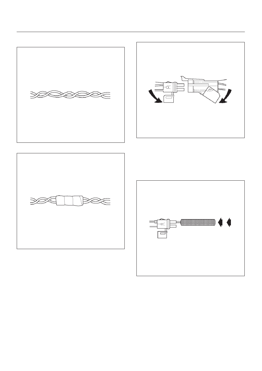
3. Twist the wires as they were before starting this

procedure.

054

4. Tape the wires with electrical tape.

055

Weather–Pack Connector

Tools Required

5-8840-0388-0 Weather–Pack II Terminal Remover

Removal Procedure

A Weather–Pack connector can be identified by a rubber
seal at the rear of the connector. This engine room
connector protects against moisture and dirt, which could
form oxidation and deposits on the terminals. This
protection is important, because of the low voltage and
the low amperage found in the electronic systems.

1. Open the secondary lock hinge on the connector.

070

2. Use tool 5-8840-0388-0 or the equivalent to remove

the pin and the sleeve terminals. Push on
5-8840-0388-0 to release.

NOTE: Do not use an ordinary pick or the terminal may
be bent or deformed. Unlike standard blade terminals,
these terminals cannot be straightened after they have
been improperly bent.

071

6E1–303

X22SE 2.2L ENGINE DRIVEABILITY AND EMISSION

3. Cut the wire immediately behind the cable seal.

072

Installation Procedure

Make certain the connectors are properly seated and all
of the sealing rings are in place when you reconnect the
leads. The secondary lock hinge provides a backup
locking feature for the connector. The secondary lock
hinge is used for added reliability. This flap should retain
the terminals even if the small terminal lock tangs are not
positioned properly.
Do not replace the Weather–Pack connections with
standard connections. Read the instructions provided
with the Weather–Pack connector and terminal
packages.

1. Replace the terminal.
2. Slip the new seal onto the wire.
3. Strip 5 mm (0.2”) of insulation from the wire.
4. Crimp the terminal over the wire and the seal.

073

5. Push the terminal and the connector to engage the

locking tangs.

6. Close the secondary locking hinge.

Com–Pack III

Com–Pack III

The Com–Pack III terminal looks similar to some
Weather–Pack terminals. This terminal is not sealed and
is used where resistance to the environment is not
required. Use the standard method when repairing a
terminal. Do not use the Weather–Pack terminal tool
5-8840-0388-0 or equivalent. These will damage the
terminals.

070

Metri–Pack

Tools Required

5-8840-0632-0 Terminal Remover

Removal Procedure

Some connectors use terminals called Metri–Pack Series
150. These may be used at the engine coolant
temperature (ECT) sensor.

1. Slide the seal (1) back on the wire.
2. Insert the 5-8840-0632-0 tool or equivalent (3) in

order to release the terminal locking tang (2).

3. Push the wire and the terminal out through the

connector. If you reuse the terminal, reshape the
locking tang.

6E1–304

X22SE 2.2L ENGINE DRIVEABILITY AND EMISSION

060

Installation Procedure

Metri–Pack terminals are also referred to as
”pull–to–seat” terminals.

1. In order to install a terminal on a wire, the wire must be

inserted through the seal (2) and through the
connector (3).

2. The terminal (1) is then crimped onto the wire.
3. Then the terminal is pulled back into the connector to

seat it in place.

061

GENERAL DESCRIPTION — ECM
AND SENSORS

58X Reference ECM Input

The engine control module (ECM) uses this signal from
the crankshaft  position (CKP) sensor to calculate engine
RPM and crankshaft position at all  speeds. The ECM
also uses the pulses on this circuit to initiate injector
pulses. If the ECM receives no pulses on this circuit, DTC
P0337 will set. If the ECM receives a number of pulses

other than the expected amount, DTC P0336 will set. The
engine will not start and run without using the 58X
reference signal.

A/C Request Signal

This signal tells the ECM when the A/C mode is selected
at the A/C control switch. The ECM uses this signal to
adjust the idle speed before turning ON the A/C clutch.
The A/C compressor will be inoperative if this signal is not
available to the ECM.
For A/C wiring diagrams and diagnosis for the A/C
electrical system, refer to A/C Clutch Circuit Diagnosis.

Crankshaft Position (CKP) Sensor

The crankshaft position (CKP) sensor provides a signal
used by the powertrain control module (ECM) to calculate
the ignition sequence. The CKP sensor initiates the 58X
reference pulses which the ECM uses to calculate RPM
and crankshaft position. For additional information,
refer to Electronic Ignition System.

0013

Camshaft Position (CMP) Sensor And
Signal

The camshaft position (CMP) sensor sends a  signal to
the ECM. The ECM uses this signal as a ”sync pulse” to
trigger the injectors in the proper sequence. The ECM
uses the CMP signal to indicate the position of the #1
piston during its power stroke. The CMP allows the ECM
to calculate true sequential fuel injection (SFI) mode of
operation. If the ECM detects an incorrect CMP signal
while the engine is running, DTC P0341 will set.
If the CMP signal is lost while the engine is running, the
fuel injection system will shift to a calculated sequential
fuel injection mode based on the last fuel injection pulse,
and the engine will continue to run. It will run in the
calculated sequential mode with a 1–in–4 chance of the
injector sequence being correct.
For further information, refer to
DTC P0341
DTC P0342.

6E1–305

X22SE 2.2L ENGINE DRIVEABILITY AND EMISSION

014RX007

Engine Coolant Temperature (ECT) Sensor

The engine coolant temperature (ECT) sensor is a
thermistor (a resistor which changes value based on
temperature) mounted in the engine coolant stream. Low
coolant temperature produces a high resistance of about
100,000 

W

 at –40

°

C (–40

°

F). High temperature causes a

low resistance of about 70 

W

 at 130

°

C (266

°

F).

The ECM supplies a 5–volt signal to the ECT sensor
through resistors internal to the ECM and then measures
the voltage after the internal resistor. This signal voltage
will be high when the engine is cold and low when the
engine is hot. By measuring the voltage, the ECM
calculates the engine coolant temperature. Engine
coolant temperature affects most of the systems that the
ECM controls.
The Tech 2 displays engine coolant temperature in
degrees. After engine start–up, the temperature should
rise steadily to about 85

°

C (185

°

F). It then stabilizes

when the thermostat opens. If the engine has not been
run for several hours (overnight), the engine coolant
temperature and intake air temperature displays should
be close to each other. A hard fault in the engine coolant
sensor circuit will set DTC P0117 or DTC P0118. An
intermittent fault will set a DTC P1114 or P1115.

0016

Electrically Erasable Programmable Read
Only Memory (EEPROM)

The electrically erasable programmable read only
memory (EEPROM) is a permanent memory chip that is
physically soldered within the ECM. The EEPROM
contains the program and the calibration information that
the ECM needs to control powertrain operation.
Unlike the PROM used in past applications, the EEPROM
is not replaceable.

Fuel Control Heated Oxygen Sensor (Pre
Catalyst)

The fuel control heated oxygen sensor (Bank 1 HO2S 1)
is mounted in the exhaust stream where it can monitor the
oxygen content of the exhaust gas. The oxygen present in
the exhaust gas reacts with the sensor to produce a
voltage output. This voltage should constantly fluctuate
from approximately 100 mV to 900 mV. The heated
oxygen sensor voltage can be monitored with a Tech 2. By
monitoring the voltage output of the oxygen sensor, the
ECM calculates the pulse width command for the
injectors to produce the proper combustion chamber
mixture.

D

Low HO2S voltage is a lean mixture which will result in
a rich command to compensate.

D

High HO2S voltage is a rich mixture which will result in
a lean command to compensate.

An open Bank 1 HO2S 1 signal circuit will set a DTC
P0134 and the Tech 2 will display a constant voltage
between 400–500 mV. A constant voltage below 300 mV
in the sensor circuit (circuit grounded) will set DTC
P0131. A constant voltage above 800 mV in the circuit will
set DTC P0132.  The ECM can also detect HO2S
response problems. If the response time of an HO2S is
determined to be too slow, the ECM will store a DTC that
indicates degraded HO2S performance.


Content   ..  249  250  251  252   ..