Opel Frontera UE. Manual - part 245


  Index      Opel     Opel Frontera UE - service repair manual 1999-2001 year


Search            


Content   ..  243  244  245  246   ..


Opel Frontera UE. Manual - part 245


6E1–278

X22SE 2.2L ENGINE DRIVEABILITY AND EMISSION

Installation Procedure

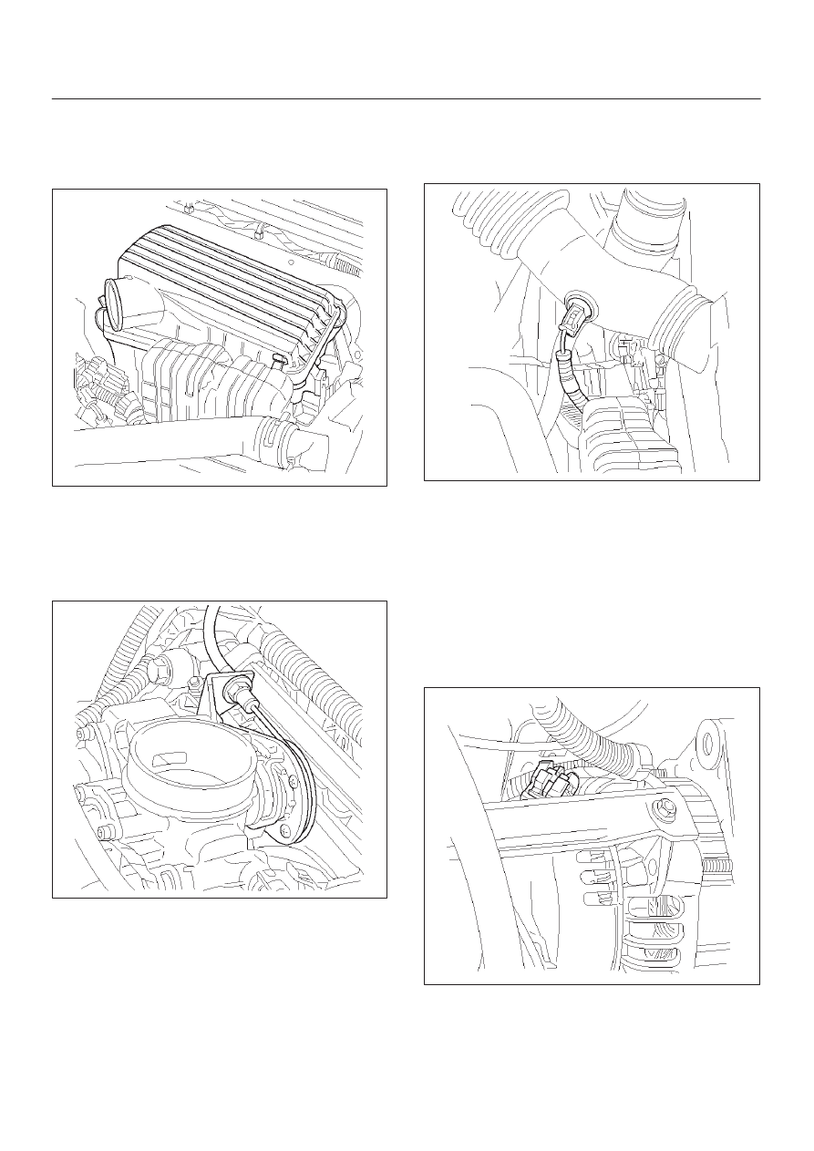
1. Connect the intake air duct at the throttle body and at

the air filter box. Make sure retaining hole is inserted
to the intake air duct bracket.

014RX019

2. Tighten retaining clamp at the throttle body and at the

air filter box.

3. Install a nut to the intake air duct bracket and tighten.
4. Connect brake booster vacuum hose to intake

manifold and to brake booster and secure them with
clamps.

014RX026

5. Install IAT sensor if necessary. Refer to Intake Air

Temperature Sensor Installation. 

6. Connect electrical connector at IAT sensor.
7. Connect the negative battery cable.

014RX011

IMPORTANT:

Use an identical replacement part in

order to replace a valve. IAC valve pintle shape and
diameter are designed for the specific application.

Knock Sensor

Removal Procedure

1. Disconnect negative battery cable.
2. Disconnect pig tail electrical connector at near the top

of generator.

014RX027

6E1–279

X22SE 2.2L ENGINE DRIVEABILITY AND EMISSION

3. Unscrew retaining bolt from Knock Sensor located

passenger side of engine block just front of starter.

014RX028

4. Remove Knock Sensor with retaining bolt.

Installation Procedure

1. Install Knock Sensor with retaining bolt.
2. Connect pig tail electrical connector.
3. Connect battery negative cable.

014RX029

Oil Pressure Switch

Removal Procedure

1. Disconnect battery negative cable.
2. Disconnect electrical connector at Oil Pressure

Switch.

014RX030

3. Unscrew Oil Pressure Switch from Oil Filter Mounting

Housing.

014RX031

6E1–280

X22SE 2.2L ENGINE DRIVEABILITY AND EMISSION

Installation Procedure

1. Install Oil Pressure Switch into Oil Filter Mounting

Housing and tighten.

2. Connect electrical connector.
3. Connect battery negative cable.

014RX028

FUEL METERING SYSTEM  Ac-

celerator Cable Assembly

Removal Procedure

1. Loosen the adjusting nut on the cable bracket

mounting on the throttle body.

2. Remove the cable clip from holding bracket.

014RX026

3. Remove accelerator control cable (on the throttle

valve end).

101RW006

4. Remove the accelerator control cable (on the

accelerator pedal end).

5. Remove the grommet.
6. Remove the accelerator control cable.

Inspection Procedure

Check the following items, and replace the control cable if
any abnormality is found:

D

The control cable should move smoothly.

D

The control cable should not be bent or kinked.

D

The control cable should be free of damage and
corrosion.

014RX032

6E1–281

X22SE 2.2L ENGINE DRIVEABILITY AND EMISSION

Installation Procedure

1. Install the accelerator control cable.
2. Install the grommet.
3. Install the accelerator control cable on the accelerator

pedal.

014RX032

4. Install the accelerator control cable on the throttle

valve.

101RW006

5. Install the cable clip to the holding bracket.

6. Adjust the accelerator cable. Refer to Accelerator

Cable Adjustment Section. 

014RX026

Accelerator Cable  Adjustment

Adjustment Procedure

1. Loosen the adjusting nut.
2. Loosen the jam nut.
3. Pull the outer cable while fully closing the throttle

valve.

4. Tighten the adjusting nut.
5. Tighten the jam nut.
6. Loosen the adjusting nut by three turns.
7. Tighten the jam nut again.
8. Manually operate valve.

IMPORTANT:

 The valve lever must return up to the

stopper screw.  If the valve lever does not reach the
stopper screw, repeat the procedure again from Step 1.

014RX026


Content   ..  243  244  245  246   ..