Opel Frontera UE. Manual - part 175


  Index      Opel     Opel Frontera UE - service repair manual 1999-2001 year


Search            


Content   ..  173  174  175  176   ..


Opel Frontera UE. Manual - part 175


STARTING AND CHARGING SYSTEM (X22SE 2.2L)

6D3–13

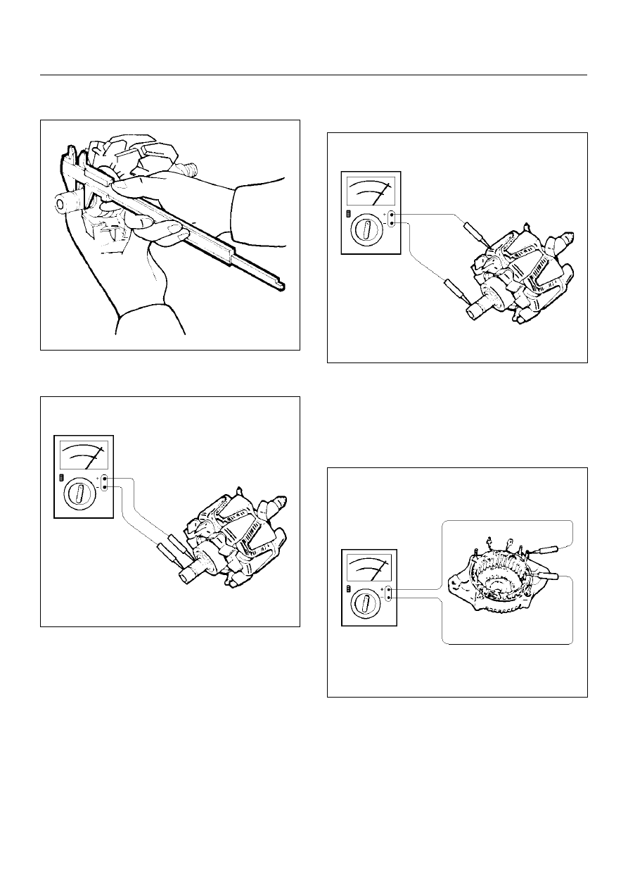
2. Measure the slip ring diameter, and replace if it 

exceeds the limit.

066RS015

3. Check resistance between slip rings, and replace if 

there is no continuity.

066RS016

4. Check for continuity between slip ring and rotor 

core.
In case of continuity, replace the rotor assembly.

066RS017

Stator Coil

1. Measure resistance between respective phases.

2. Measure insulation resistance between stator coil 

and core with a mega–ohmmeter.
If less than standard, replace the coil.

066RS018

6D3–14

STARTING AND CHARGING SYSTEM (X22SE 2.2L)

Brush

Measure the brush length.
If more than limit, replace the brush.

Standard: 5 mm (0.20in)

066RW009

Rectifier Assembly

Check for continuity across “1" and “2" in the 

×

 100W 

range of multimeter.

066RW011

Change polarity, and make sure that there is continuity 
in one direction, and not in the reverse direction.  In 
case of continuity in both directions, replace the rectifier 
assembly.

Reassembly

To reassemble, follow the disassembly steps in the 
reverse order, noting the following points:

1. Install pulley on the rotor.

Clamp pulley to the vise, and tighten nut to the 
specified torque.

Torque: 40 N·m (4.1 kg·m/30 lbft)

066RS010

STARTING AND CHARGING SYSTEM (X22SE 2.2L)

6D3–15

Main Data and Specifications

General Specifications

Battery voltage

V

12

Rated output

A

100

Direction of rotation

(as viewed from pulley side)

Clockwise

Maximum speed

rpm

18000

6E1–1

X22SE 2.2L ENGINE DRIVEABILITY AND EMISSION

FRONTERA

ENGINE

ENGINE DRIVEABILITY AND EMISSIONS

CONTENTS

SPECIFICATIONS

6E1–6

. . . . . . . . . . . . . . . . . . . . . 

TIGHTENING SPECIFICATIONS

6E1–6

. . . . . . . . 

DIAGRAMS AND SCHEMATICS

6E1–7

. . . . . . . . . . 

ECM WIRING DIAGRAM (1 of 10)

6E1–7

. . . . . . . 

ECM WIRING DIAGRAM (2 of 10)

6E1–8

. . . . . . . 

ECM WIRING DIAGRAM (3 of 10)

6E1–9

. . . . . . . 

ECM WIRING DIAGRAM (4 of 10)

6E1–10

. . . . . . . 

ECM WIRING DIAGRAM (5 of 10)

6E1–11

. . . . . . . 

ECM WIRING DIAGRAM (6 of 10)

6E1–12

. . . . . . . 

ECM WIRING DIAGRAM (7 of 10)

6E1–13

. . . . . . . 

ECM WIRING DIAGRAM (8 of 10)

6E1–14

. . . . . . . 

ECM WIRING DIAGRAM (9 of 10)

6E1–15

. . . . . . . 

ECM WIRING DIAGRAM (10 of 10)

6E1–16

. . . . . . 

ECM PINOUTS

6E1–17

. . . . . . . . . . . . . . . . . . . . . . . . . 

ECM Pinout Table, 32–Pin Red Connector
 – Row ”A”

6E1–17

. . . . . . . . . . . . . . . . . . . . . . . . . . . . 

ECM Pinout Table, 32–Pin Red Connector
 – Row ”B”

6E1–18

. . . . . . . . . . . . . . . . . . . . . . . . . . . . 

ECM Pinout Table, 32–Pin White Connector
 – Row ”C”

6E1–19

. . . . . . . . . . . . . . . . . . . . . . . . . . . . 

ECM Pinout Table, 32–Pin White Connector
 – Row ”D”

6E1–20

. . . . . . . . . . . . . . . . . . . . . . . . . . . . 

ECM Pinout Table, 32–Pin White Connector
 – Row ”E”

6E1–21

. . . . . . . . . . . . . . . . . . . . . . . . . . . . 

ECM Pinout Table, 32–Pin White Connector
 – Row ”F”

6E1–22

. . . . . . . . . . . . . . . . . . . . . . . . . . . . 

COMPONENT LOCATOR

6E1–23

. . . . . . . . . . . . . . . . 

Undercarriage Component Locator Table

6E1–26

Fuse And Relay Panel (Underhood
 Electrical Center)

6E1–26

. . . . . . . . . . . . . . . . . . . . . 

DIAGNOSIS Strategy–Based Diagnostics

6E1–27

Strategy–Based Diagnostics

6E1–27

. . . . . . . . . . . . 

DTC Stored

6E1–27

. . . . . . . . . . . . . . . . . . . . . . . . . . . 

No DTC

6E1–27

. . . . . . . . . . . . . . . . . . . . . . . . . . . . . . 

No Matching Symptom

6E1–27

. . . . . . . . . . . . . . . . . 

Intermittents

6E1–27

. . . . . . . . . . . . . . . . . . . . . . . . . . 

No Trouble Found

6E1–27

. . . . . . . . . . . . . . . . . . . . . 

Verifying Vehicle Repair

6E1–27

. . . . . . . . . . . . . . . . 

GENERAL SERVICE INFORMATION

6E1–27

. . . . . . 

Non–OEM Parts

6E1–27

. . . . . . . . . . . . . . . . . . . . . . . 

Environment

6E1–28

. . . . . . . . . . . . . . . . . . . . . . . . . . 

Emissions Control Information Label

6E1–28

. . . . . 

Maintenance Schedule

6E1–28

. . . . . . . . . . . . . . . . . 

Visual/Physical Engine Compartment
 Inspection

6E1–28

. . . . . . . . . . . . . . . . . . . . . . . . . . . . 

Basic Knowledge Of Tools Required

6E1–28

. . . . . 

SERIAL DATA COMMUNICATIONS

6E1–28

. . . . . . . 

Class II Serial Data  Communications

6E1–28

. . . . 

ON–BOARD DIAGNOSTIC (OBD)

6E1–28

. . . . . . . . . 

On–Board Diagnostic Tests

6E1–28

. . . . . . . . . . . . . 

Comprehensive Component Monitor
 Diagnostic Operation

6E1–29

. . . . . . . . . . . . . . . . . . 

Common OBD Terms

6E1–29

. . . . . . . . . . . . . . . . . . 

The Diagnostic Executive

6E1–30

. . . . . . . . . . . . . . . 

DTC Types

6E1–31

. . . . . . . . . . . . . . . . . . . . . . . . . . . 

Verifying Vehicle Repair

6E1–32

. . . . . . . . . . . . . . . . 

Reading Diagnostic Trouble Codes Using
 A Tech 2 Scan Tool

6E1–32

. . . . . . . . . . . . . . . . . . . . 

Tech 2 Features

6E1–34

. . . . . . . . . . . . . . . . . . . . . . . 

Getting Started

6E1–34

. . . . . . . . . . . . . . . . . . . . . . . . 

Operating Procedure (Example)

6E1–35

. . . . . . . . . 

DTC Modes

6E1–36

. . . . . . . . . . . . . . . . . . . . . . . . . . . 

DTC Information Mode

6E1–36

. . . . . . . . . . . . . . . . . 

Miscellaneous Test

6E1–37

. . . . . . . . . . . . . . . . . . . . 

Lamps Test

6E1–37

. . . . . . . . . . . . . . . . . . . . . . . . . . . 

Relays Test

6E1–38

. . . . . . . . . . . . . . . . . . . . . . . . . . . 

EVAP Test

6E1–40

. . . . . . . . . . . . . . . . . . . . . . . . . . . . 

Idle Air Control System Test

6E1–40

. . . . . . . . . . . . . 

Fuel System Test

6E1–42

. . . . . . . . . . . . . . . . . . . . . . 

EGR Control Test

6E1–43

. . . . . . . . . . . . . . . . . . . . . . 

Injector Balance Test

6E1–43

. . . . . . . . . . . . . . . . . . . 

Plotting Snapshot Graph

6E1–44

. . . . . . . . . . . . . . . 

Plotting Graph Flow Chart (Plotting graph
 after obtaining vehicle information)

6E1–45

. . . . . . 

Flow Chart for Snapshot Replay (Plotting
 Graph)

6E1–46

. . . . . . . . . . . . . . . . . . . . . . . . . . . . . . . 

PRIMARY SYSTEM–BASED DIAGNOSTICS

6E1–47

Primary System–Based Diagnostics

6E1–47

. . . . . 

Fuel Control Heated Oxygen Sensors 

6E1–47

. . . 

HO2S Heater

6E1–47

. . . . . . . . . . . . . . . . . . . . . . . . . 

ON–BOARD DIAGNOSTIC (OBD) SYSTEM
 CHECK

6E1–48

. . . . . . . . . . . . . . . . . . . . . . . . . . . . . . . 

Circuit Description

6E1–48

. . . . . . . . . . . . . . . . . . . . . 

Diagnostic Aids

6E1–48

. . . . . . . . . . . . . . . . . . . . . . . . 

Test Description

6E1–48

. . . . . . . . . . . . . . . . . . . . . . . 

A/C CLUTCH CONTROL CIRCUIT
 DIAGNOSIS

6E1–50

. . . . . . . . . . . . . . . . . . . . . . . . . . . 

Circuit Description

6E1–50

. . . . . . . . . . . . . . . . . . . . . 

Diagnostic Aids

6E1–50

. . . . . . . . . . . . . . . . . . . . . . . . 

A/C Clutch Diagnosis

6E1–51

. . . . . . . . . . . . . . . . . . 

ELECTRONIC IGNITION SYSTEM
 DIAGNOSIS

6E1–53

. . . . . . . . . . . . . . . . . . . . . . . . . . . 

VISUAL CHECK OF THE EVAPORATIVE
 EMISSION CANISTER

6E1–53

. . . . . . . . . . . . . . . . . . 

SECTION


Content   ..  173  174  175  176   ..