Index Opel Opel Frontera UE - service repair manual 1999-2001 year
Search
Content .. 1667 1668 1669 1670 ..
Opel Frontera UE. Manual - part 1669
8D–106
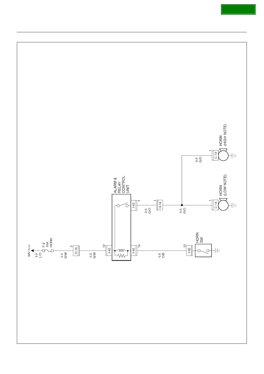
WIRING SYSTEM
Circuit Diagram
D08R100115
SECTION