Content .. 1642 1643 1644 1645 ..
Opel Frontera UE. Manual - part 1644
8D–6
WIRING SYSTEM
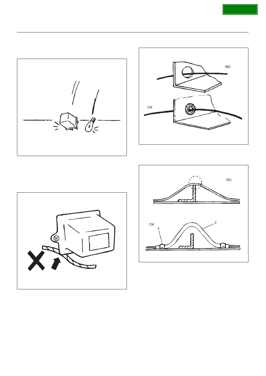
Parts Handling
Be careful when handling electrical parts. They should not
be dropped or thrown, because short circuiting or other
damage may result.
D08RW138
Cable Harness
1. When installing the parts, be careful not to pinch or
wedge the wiring harness.
2. All electrical connections must be kept clean and
tight.
D08RW139
3. Use a grommet or guard tube to protect the wiring
harness from contacting a sharp edge or surface.
D08RW139
4. Position the wiring harness with enough clearance
from the other parts and guard the wiring harness with
a vinyl tube (2) and clips (1) to avoid direct contact.
D08RW141