Opel Frontera UE. Manual - part 1601


  Index      Opel     Opel Frontera UE - service repair manual 1999-2001 year


Search            


Content   ..  1599  1600  1601  1602   ..


Opel Frontera UE. Manual - part 1601


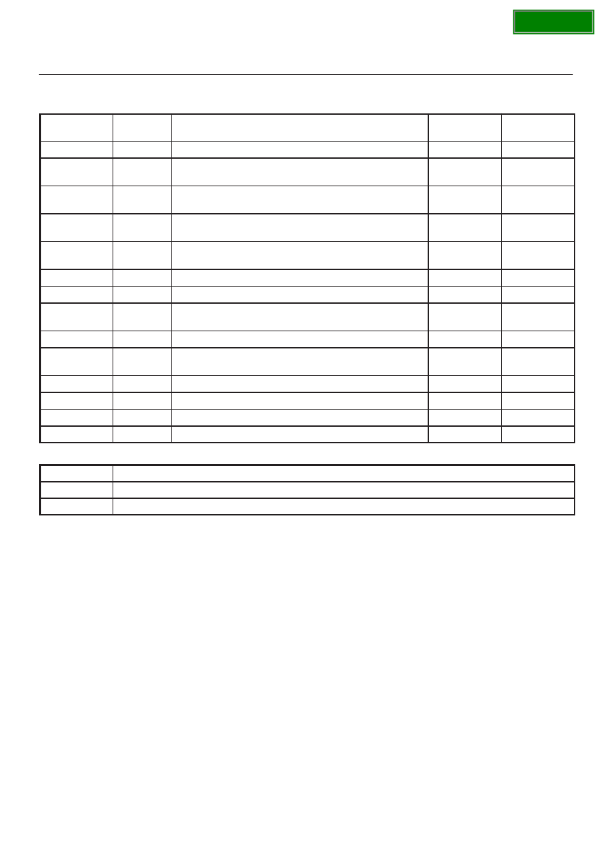
7A1–26 TRANSMISSION CONTROL SYSTEM (4L30–E)

Diagnostic Trouble Code (DTC)
Identification

DTC

NUMBER

FLASHING

CODE

DTC NAME

DTC TYPE

“CHECK

TRANS”

P0218

71

Transmission Fluid Over Temperature

D

P0705

73

Transmission Range Switch (Mode Switch) Illegal
Position

D

P0706

74

Transmission Range Switch (Mode Switch) Perfor-
mance

D

P0712

75

Transmission Fluid Temperature (TFT) Sensor Circuit
Low Input

D

P0713

76

Transmission Fluid Temperature (TFT) Sensor Circuit
High Input

D

P0719

77

TCC Brake Switch Circuit High (Stuck ON)

D

P0722

78

Transmission Output Speed Sensor (OSS) Low Input

C

Flash

P0723

79

Transmission Output Speed Sensor (OSS)
Intermittent

C

Flash

P0730

81

Transmission Incorrect Gear Ratio

C

Flash

P0748

82

Pressure Control Solenoid (PCS) (Force Motor)
Circuit Electrical

C

Flash

P0753

83

Shift Solenoid A Electrical

C

Flash

P0758

84

Shift Solenoid B Electrical

C

Flash

P1850

88

Brake Band Apply Solenoid Malfunction

D

P1860

89

TCC Solenoid Electrical

C

Flash

DTC TYPE

DEFINITION

C

Flashing Check Trans on 1st failure

D

No lamps

SECTION

TRANSMISSION CONTROL SYSTEM (4L30–E)

7A1–27

DTC P0218/Flashing Code 71 Transmission Fluid Over Temperature

D07R100026

Circuit Description

The Transmission Fluid Temperature (TFT) sensor is a
thermister that controls the signal voltage to the PCM.
The PCM supplies a 5–volt reference to the sensor on
circuit RED/BLK. When the transmission fluid is cold, the
sensor resistance is high and the PCM will sense high
signal voltage.  As the fluid temperature warms to a
normal transmission operating temperature of 100

°

C

(212

°

F), the sensor resistance becomes less and the

voltage decreases to 1.5 to 2.0 volts.
This DTC detects a high transmission temperature for a
long period of time.  This is a type “D” DTC.

Conditions For Setting The DTC

D

No TFT DTCs P0712 (Flashing Code 75) or P0713
(Flashing Code 76).

D

TFT is greater than 135

°

C (275

°

F).

D

All conditions met for 21 seconds.

Action Taken When The DTC Sets

D

Hot mode TCC Shift Pattern.

D

The PCM will not illuminate the CHECK TRANS
Lamp.

D

ATF Lamp ON. (greater than 145

°

C (293

°

F)) 

D

Disable E–side TCC OFF request.

Conditions For Clearing The DTC

D

The DTC can be cleared from the PCM history by
using a scan tool.

D

The DTC will be cleared from history when the vehicle
has achieved 40 warm–up cycles without a failure
reported.

D

The PCM will cancel the DTC default actions when
the fault no longer exists and the ignition is cycled “off”
long enough to power down the PCM.

Diagnostic Aids

D

Inspect the wiring for poor electrical connections at
the PCM and at the transmission 7–way connector.
Look for possible bent, backed out, deformed or
damaged terminals. Check for weak terminal tension
as well.

Also check for a chafed wire that could short to bare
metal or other wiring.  Inspect for a broken wire inside
the insulation.

D

When diagnosing for a possible intermittent short or
open condition, move the wiring harness while
observing test equipment for a change.

D

Check harness routing for a potential short to ground
in circuit RED/BLK.

D

Scan tool TFT sensor temperature should rise
steadily to about 100

°

C (212

°

F), then stabilize.

D

Check for a “skewed” (mis–scaled) sensor by
comparing the TFT sensor temperature to the
ambient temperature after a vehicle cold soak.  A
“skewed” sensor can cause delayed garage shifts or
TCC complaints.

D

Check for a possible torque converter stator problem.

D

Verify customer driving habits, trailer towing, etc.

Test Description

The numbers below refer to the step numbers on the
diagnostic chart.
2. This test checks for a “skewed” sensor or shorted

circuit.

3. This test simulates a TFT DTC P0713.

SECTION

7A1–28 TRANSMISSION CONTROL SYSTEM (4L30–E)

DTC P0218/Flashing Code 71 Transmission Fluid Over Temperature 

Step

Action

Yes

No

1

Perform the following checks:

D

Check for possible engine system problems.

D

Transmission fluid checking procedure.  Refer to 

Checking

Transmission Fluid Level and Condition in Automatic
Transmission (4L30–E) Section.

Were the checks performed?

Go to 

Step 2

Refer to 

“Engine

Manual”

2

1. Install the scan tool.
2. With the engine “off”, turn the ignition switch “on”.

NOTE: Before clearing DTC(s), use the scan tool to record “Failure
Records” for reference, as data will be lost when “Clear Info”
function is used.

3. Record the DTC “Failure Records”.

Is the TFT sensor signal voltage less than 1.54 volts?

Go to 

Step 3

Go to 

Diagnostic
Aids

3

1. Turn the ignition “off”.
2. Disconnect the transmission 7–way connector E–54

(additional DTCs may set).

3. With the engine “off”, turn the ignition switch “on”.

Is the TFT sensor signal voltage greater than 4.92 volts?

Go to 

Internal

Wiring Harness

Check

Go to 

Step 4

4

Inspect/repair circuit RED/BLK for a short to ground.

Was a problem found?

Go to 

Step 6

Go to 

Step 5

5

1. Inspect the PCM for poor connections.
2. Replace the PCM if no poor connections were found.

Is the replacement complete?

Go to 

Step 6

6

1. After the repair is complete, use the scan tool to select “DTC”,

then “Clear Info” function and ensure the following conditions
are met:
TFT is less than 125

°

C (257

°

F) for at least 10 seconds.

2. Review the scan tool “DTC Info”.

Has the last test failed or is the current DTC displayed?

Begin diagnosis

again

Go to 

Step 1

Repair verified
Exit DTC table

SECTION

TRANSMISSION CONTROL SYSTEM (4L30–E)

7A1–29

DTC P0705/Flashing Code 73 Transmission Range Switch (Mode Switch) Illegal
Position

D07R100027

Circuit Description

D

The range switch supplies the Powertrain Control
Module (PCM) with information regarding the selector
lever position: P, R, N, D 3, 2 or L.  The selector lever
position is indicated by the state of four ON/OFF
contracts.  The range switch is located on one side of
the transmission.  It is on the transmission manual
shaft and is fixed to the main case.

D

The range switch is also used to provide the
information P or N to the engine crank wiring. The
engine can be cranked only if connector E–53
terminal 4(H) is connected to terminal 1(E) which is
connected to ground.

D

The range switch is also used to provide the backup
lamp power in reverse.  This is the reason why the
range switch is supplied through a 15A fuse (TURN,
BACK UP).  This fuse can burn due to a short circuit in
the back up lamp.

This DTC detects when a fuse is open or the range switch
circuit does not work.  This is a type “D” DTC.

Conditions For Setting The DTC

D

Range switch illegal positions met for 5 seconds.

Action Taken When The DTC Sets

D

Default to D position.

D

Inhibit torque management.

D

Turn Force Motor off.

D

Maximum line pressure.

D

The PCM will not illuminate the CHECK TRANS
Lamp.

Conditions For Clearing The DTC

D

The DTC can be cleared from the PCM history by
using a scan tool.

D

The DTC will be cleared from history when the vehicle
has achieved 40 warmup cycles without a failure
reported.

D

The PCM will cancel the DTC default actions when
the fault no longer exists and the ignition is cycled “off”
long enough to power down the PCM.

SECTION


Content   ..  1599  1600  1601  1602   ..