Opel Frontera UE. Manual - part 1556


  Index      Opel     Opel Frontera UE - service repair manual 1999-2001 year


Search            


Content   ..  1554  1555  1556  1557   ..


Opel Frontera UE. Manual - part 1556


6E–439

6VD1 3.2L ENGINE DRIVEABILITY AND EMISSIONS

3. Disconnect the electrical connectors:

D

Throttle position (TP) sensor.

D

Intake air temperature (IAT) sensor.  Refer to 

Intake

Air Temperature Sensor section.

060RY00014

4. Disconnect the vacuum hose below the air horn.
5. Remove the intake air duct clamp.
6. Disconnect the intake air duct.
7. Disconnect the coolant lines from the throttle body.
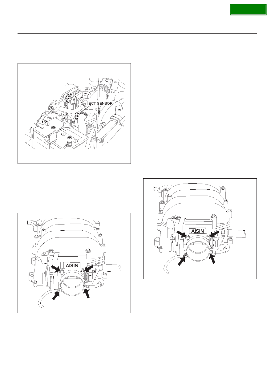
8. Remove the bolts from the common chamber.
9. Remove the throttle body from the common chamber.

10. Remove the gasket from the common chamber.

025RY00004

11. Remove the TP sensor.  Refer to 

Throttle Position

(TP) Sensor section.

Inspection Procedure

NOTE: Do not use solvent of any type when you clean the
gasket surfaces on the intake manifold and the throttle
body assembly.  The gasket surfaces and the throttle
body assembly may be damaged as a result.

D

If the throttle body gasket needs to be replaced,
remove any gasket material that may be stuck to the
mating surfaces of the manifold.

D

Do not leave any scratches in the aluminum casting.

Installation Procedure

1. Install the TP sensor.  Refer to 

Throttle Position (TP)

Sensor section.

2. Install the gasket on the common chamber.
3. Install the throttle body on the common chamber.
4. Secure the gasket and the throttle body with the four

bolts.

D

The vacuum lines must be properly routed under
the throttle body before tightening the mounting
bolts.

Tighten

D

Tighten the throttle body mounting bolts to 10
N·m (87 lb in).

025RY00004

5. Install the coolant lines.
6. Connect all the vacuum lines.
7. Install the intake air duct.
8. Tighten the intake air duct clamp.

SECTION

6E–440

6VD1 3.2L ENGINE DRIVEABILITY AND EMISSIONS

9. Connect all the electrical connectors:

D

Throttle position (TP) sensor.

D

Intake air temperature (IAT) sensor.  Refer to 

Intake

Air Temperature Sensor section.

060RY00020

10. Install the accelerator cable assembly.  Refer to

Accelerator Cable in Engine Speed Control System
section.

11. Fill the cooling system.  Refer to 

Cooling System

section.

12. Install the negative battery cable.

Electronic Ignition System

Removal Procedure

1. Disconnect the negative battery cable.
2. Disconnect the ignition coil connector at the ignition

coil assemblies.

3. Remove the two screws that secure the ignition coil

assemblies to the rocker cover.

060RY022

Legend

(1) Ignition Coil Connectors
(2) Bolts
(3) Ignition Coil Assemblies

4. Remove the ignition coil assemblies and the spark

plug boot from the spark plug.

D

Twist the ignition coil assemblies while pulling it
straight up.

5. Use the appropriate spark plug socket in order to

remove the spark plug from the engine.

Installation Procedure

NOTE: The plug must thread smoothly into the cylinder
head and be fully seated.  Use a thread chaser if
necessary to clean the threads in the cylinder head.
Cross-threading or failure to fully seat the spark plug can
cause plug overheating, exhaust blow-by gases, or
thread damage.  Do not overtighten the spark plugs.  Over
tightening can cause aluminum threads to strip.

1. Install the spark plug in the engine.  Use the

appropriate spark plug socket.

Tighten

D

Tighten the spark plug to 18 N·m (13 lb ft.).

2. Install the ignition coil assemblies and spark plug boot

over the spark plug.

CAUTION: Ignition coil assembly #6 is different
from ignition coil assembly #1 to #5. Ignition coil
assemblies #6 is short type. Be careful it when
installing ignition coil assembly of #6.

060RY00002

Legend

(1) Long Type Ignition Coil Assemblies (#1 

 #5)

(2) Short Type Ignition Coil Assembly (#6)

SECTION

6E–441

6VD1 3.2L ENGINE DRIVEABILITY AND EMISSIONS

3. Install ignition coil assemblies and tighten the fixing

bolts to the specified torque.

Torque: 4 N·m (35.4 Ib in)

060RY022

Legend

(1) Ignition Coil Connectors
(2) Bolts
(3) Ignition Coil Assemblies

4. Connect the ignition coil connector at the ignition coil

assemblies.

5. Connect the negative battery cable.

Catalytic Converter

Removal and Installation Procedure

Refer to 

Engine Exhaust in Engine section.

Air Conditioning  Thermo Relay

Removal Procedure

1. Remove the fuse and relay box cover from under the

hood.

2. Consult the diagram on the cover to determine which

is the correct relay.

3. Insert a small screwdriver into the catch slot on the

forward side of the fuel pump relay.

D

The screwdriver blade will release the catch inside.

D08RW131

4. Pull the relay straight up and out of the fuse and relay

box.

014RY00007

SECTION

6E–442

6VD1 3.2L ENGINE DRIVEABILITY AND EMISSIONS

Installation Procedure

1. Insert the relay into the correct place in the fuse and

relay box with the catch slot facing forward.

2. Press down until the catch engages.

D

An audible “click” will be heard.

3. Install the fuse and relay box cover.

014RY00007

EVAP Canister

Removal Procedure

1. Disconnect the negative battery cable.
2. Disconnect the two hoses from the EVAP canister.

014RW117

3. Disconnect the fuel vapor connector and the purge

hose from the EVAP canister vent solenoid.

014RW130

4. Remove the two retaining bolts the EVAP canister to

the mounting bracket on the cross member.

014RW131

SECTION


Content   ..  1554  1555  1556  1557   ..