Opel Frontera UE. Manual - part 1510


  Index      Opel     Opel Frontera UE - service repair manual 1999-2001 year


Search            


Content   ..  1508  1509  1510  1511   ..


Opel Frontera UE. Manual - part 1510


6E–255

6VD1 3.2L ENGINE DRIVEABILITY AND EMISSIONS

Diagnostic Trouble Code (DTC) P0406  EGR High Voltage
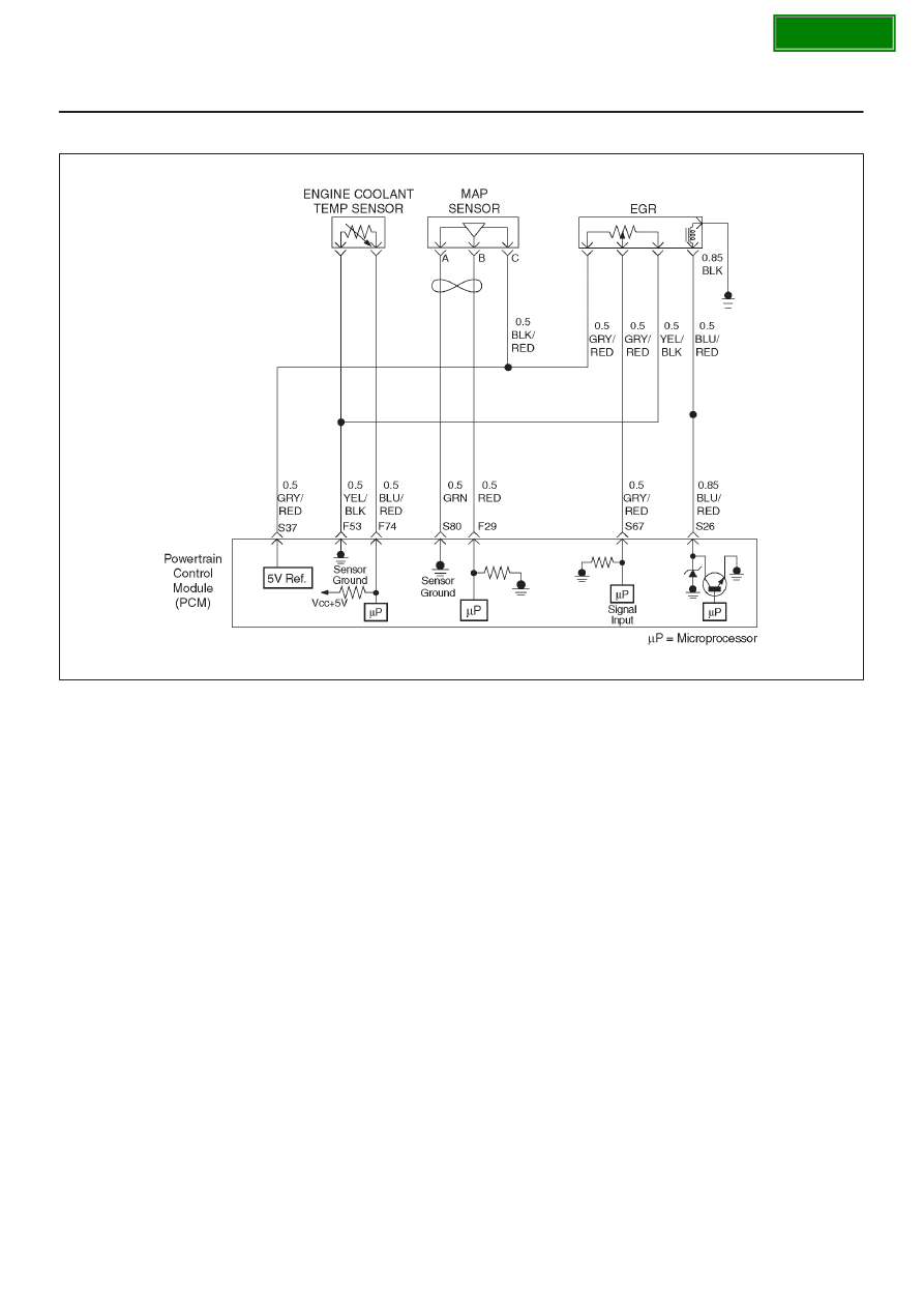
060R100136

Circuit Description

The powertrain control module (PCM) monitors the EGR
valve pintle position input to ensure that the valve
responds properly to command from the PCM. If current
pintle  position voltage indicates more than 4.8 V and last
more than 10 seconds, then the PCM will set DTC P0406.

Conditions for Setting the DTC

D

Ignition voltage is between 11 and 16 volts.

D

Intake Air temp is more than 3

°

C (37.4

°

F).

D

EGR pintle position is more than 99% and last more
than 10 sec.

Action Taken When the DTC Sets

D

The PCM will ON the MIL after second trip with
detected the fault.

D

The PCM will store conditions which were present
when the DTC was set as Freeze Frame and in Failure
Records data.

Conditions for Clearing the MIL/DTC

D

The PCM will turn the MIL “OFF” on the third
consecutive trip cycle during which the diagnostic has
been run and the fault condition is no longer present.

D

A history DTC P0402 will clear after 40 consecutive
warm-up cycles have occurred without a fault.

D

DTC P0404 can be cleared by using the Tech 2 “Clear
Info” function.

Diagnostic Aids

Check for the following conditions:

D

Poor connection or damaged harness – Inspect the
wiring harness for damage. If the harness appears to
be OK, observe the EGR actual position display on the
Tech 2 while moving connectors and wiring harnesses
related to EGR valve. A change in the display will
indicate the location of the fault.

SECTION

6E–256

6VD1 3.2L ENGINE DRIVEABILITY AND EMISSIONS

DTC P0406 – EGR High Voltage


Step

Action

Value(s)

Yes

No

1

Was the “On-Board Diagnostic (OBD) System Check”
performed?

Go to 

Step 2

Go to 

OBD

System

Check

2

1. Ignition “ON”, engine “OFF”, review and record

Tech 2 Failure Records Data.

2. Operate the vehicle within Failure Records

conditions as noted.

3. Using a Tech 2, monitor “DTC” info for DTC P0406

until the DTC P0406 test runs. Note the result.

Does the Tech 2 indicates DTC P0406 failed this
ignition?

Go to 

Step 3

Refer to

Diagnostic

Aids

3

1. Disconnect the EGR valve harness connector.
2. Inspect the EGR valve and connectors for damaged

pin or terminals.

Were there any damaged pins or terminals?

Go to 

Step 4

Go to 

Step 5

4

Repair the damaged pin or terminal.

Is the action complete?

Verify repair

Is the action

complete?

5

1. Disconnect the EGR harness connector.
2. Ignition “ON”.
3. At the EGR valve, use a DVM to check the voltage

at the 5 volt reference wire (BLU/RED).

Did the DVM indicate the specified value?

4–6 V

Go to 

Step 8

Go to 

Step 6

6

1. Ignition “ON”.
2. At the PCM connector, backprobe with a DVM at the

5 volt reference for the EGR valve.

Did the DVM indicate the specified value?

4–6 V

Go to 

Step 7

Go to 

Step 16

7

Repair the open 5 volt reference circuit

Is the action complete?

Verify repair

8

1. Ignition “OFF”
2. Disconnect the EGR  harness.
3. Use a DVM to check for an resistance between 5 V

reference and Sensor Ground at EGR sensor
terminals.

NOTE: J-35616 Connector Test Adapter Kit may be
useful for gaining access to the recessed pins on the
valve.

Was the measured resistance in range?

5 to 5 K

W

Go to 

Step 9

Go to 

Step 15

9

1. Ignition “OFF”.
2. Disconnect the EGR harness.
3. Use a DVM to check for an resistance between

Sensor Ground and Signal Wire at EGR sensor
terminal.

Is there an open circuit?

Go to 

Step 15

Go to 

Step 10

10

1. Ignition “OFF”.
2. Disconnect the EGR harness at PCM connector.
3. Use a DVM to check for shorted wire between S37

and F53.

Is there a shorted wire?

Go to 

Step 14

Go to 

Step 11

SECTION

6E–257

6VD1 3.2L ENGINE DRIVEABILITY AND EMISSIONS

DTC P0406 – EGR High Voltage

  (Cont'd)

Step

No

Yes

Value(s)

Action

11

1. Ignition “ON”.
2. Use a DVM to backprobe at  terminal Connector of

EGR valve for voltage.

Was measured voltage more than 4.8 V?

more than

4.8 V

Go to 

Step 12

Go to 

Step 12

12

1. Ignition “ON”.
2. Stay the EGR harness connected.
3. Check voltage by backprobing at PCM S37

terminal.

Was voltage more than 4.8 V?

4.8 V

Go to 

Step 16

Go to 

Step 13

13

1. Locate short circuit at EGR harness between

BLU/RED to GRY/RED or GRY/RED to YEL,
BLU/RED.

2. Replace EGR harness.

Is the action complete?

Verify repair

14

Replace EGR harness.

Is the action complete?

Verify repair

15

Replace the EGR valve.

Does DTC P1404 still fail “DTC test on the Tech 2?

Go to 

Step 16

Verify repair

16

Replace the PCM.

IMPORTANT: The replacement PCM must be
programmed.  Refer to 

On-Vehicle Service in

Powertrain Control Module and Sensors for
procedures.

And also refer to latest Service Bulletin.

Check to see if the Latest software is released or not.
And then Down Load the LATEST PROGRAMMED
SOFTWARE to the replacement PCM.

Is the action complete?

Verify repair

SECTION

6E–258

6VD1 3.2L ENGINE DRIVEABILITY AND EMISSIONS

Diagnostic Trouble Code (DTC) P0502 VSS Circuit Low Input

060R100071

Circuit Description

The vehicle speed sensor has a magnet rotated by the
transmission output shaft.  Attached to the sensor is a hall
effect circuit the interacts with the magnetic field treated
by the rotating magnet.  A 12-volt operating supply for the
speed sensor hall circuit is supplied from the meter fuse.
The VSS pulses to ground the 9-volt signal sent from the
powertrain control module (PCM) on the reference circuit.
The PCM interprets vehicle speed by the number of
pulses to ground per second on the reference circuit.

Conditions for Setting the DTC

D

Engine is running.

D

Engine speed is between 1800 RPM and 2500 RPM.

D

Throttle angle is between 10% and 40%.

D

Engine load is greater than 50 kPa.

D

PCM detects no VSS signal for 12.5 seconds over a
period of 15 seconds.

Action Taken When the DTC Sets

D

The PCM will ON the MIL after second trip with
detected the fault.

D

The PCM will store conditions which were present
when the DTC was set as Freeze Frame and in the
Failure Records data.

Conditions for Clearing the MIL/DTC

D

The PCM will turn the MIL “OFF” on the third
consecutive trip cycle during which the diagnostic has
been run and the fault condition is no longer present.

D

A history DTC P0502 will clear after 40 consecutive
warm-up cycles have occurred without a fault.

D

DTC P0502 can be cleared by using the Tech 2 “Clear
Info” function.

Test Description

Number(s) below refer to the step number(s) on the
Diagnostic Chart.
10. To avoid backprobing the VSS and possibly

damaging a seal or terminal, the VSS output can be
tested at the point where the transmission harness
connects to the engine harness.  Power and ground
are applied by jumpers to the VSS through the
connectors which are located to the rear of the air
cleaner assembly.  The VSS signal is monitored
with a DVM as the rear driveshaft turns.  The
wheels can be turned to rotate the driveshaft, or in
2-wheels-drive vehicles the driveshaft can be turned
directly.

SECTION


Content   ..  1508  1509  1510  1511   ..