Opel Frontera UE. Manual - part 139


  Index      Opel     Opel Frontera UE - service repair manual 1999-2001 year


Search            


Content   ..  137  138  139  140   ..


Opel Frontera UE. Manual - part 139


POWER-ASSISTED BRAKE SYSTEM

5C–41

302RS019

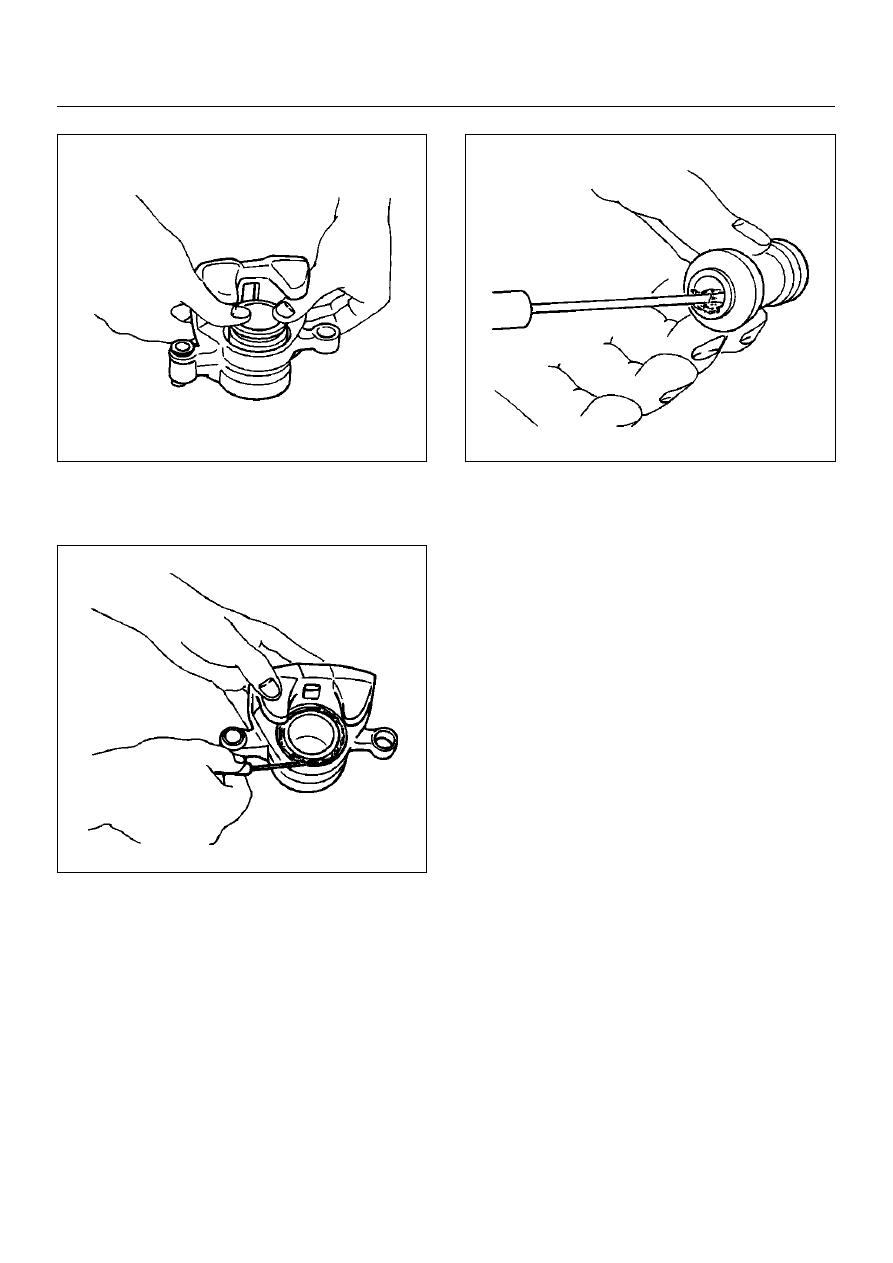
5. Apply special grease (approximately 1 g) to the 

piston and attach the dust boot to the piston and 
caliper. Insert the dust boot ring into the dust boot.

302RS020

6. Install guide bolt and lock bolt dust boot.

7. Install the dust boot on the support bracket after 

applying special grease (approximately 1 g) onto the 
dust boot inner surface.  Apply special grease onto 
the lock bolt and guide bolt setting hole of the 
support bracket.

302RS021

8. Install lock bolt and guide bolt and tighten the bolt to 

the specified torque.

Torque: 74 N·m (7.5 kg·m/54 lbft)

5C–42

POWER-ASSISTED BRAKE SYSTEM

Main Data and Specifications

General Specifications

Torque Specifications

E05RX009

Type

Floating, pin slide

Pad dimension

55 cm

2

 (8.52 in

2

)

Adjusting method

Self–adjusting

Piston diameter

60.33 mm (2.38 in)

Disc type

Ventilated

Disc thickness

26 mm (1.02 in)

Disc effective diameter

222 mm (8.74 in)

POWER-ASSISTED BRAKE SYSTEM

5C–43

Rear Disc Brake Pads

Brake Pads Inspection

Check the outer pads by looking at each caliper from 
above. Check the thickness on the inner pad by looking 
down through the inspection hole in the top of the 
caliper. Whenever the pad is worn to about the 
thickness of the pad base, the pad should be removed 
for further measurements. The pad should be replaced 
anytime the pad thickness (1) is worn to within 1.0 mm 
(0.039 in) of the pad itself.
The disc pads have a wear indicator that makes a noise 
when the pad wears to where replacement is required.

Minimum limit (1): 1.0 mm (0.039 in)

302RW016

Brake Pads and Associated Parts

306RW001

Legend

EndOFCallout

(1) Caliper Assembly
(2) Clip

(3) Lock Bolt
(4) Pad Assembly

5C–44

POWER-ASSISTED BRAKE SYSTEM

Removal

NOTE:  If a squealing noise occurs from the rear brake 
while driving, check the pad wear indicator plate. If the 
indicator plate contacts the rotor, the disc pad assembly 
should be replaced.

• Draw out two–thirds of the brake fluid from the 

reservoir.

• Raise the vehicle and support it with suitable safety 

stands.

1. Remove wheel and tire assembly, referring to 

“Wheels and Tires System" in Section 3E.

2. Remove lock bolt (1)

306RW002

3. Rotate caliper assembly and support the caliper 

assembly so that the brake hose is not stretched or 
damaged.

4. Remove pad assembly with shim.

5. Remove clip.

Installation

1. Install clip (2).

306RW003

2. Apply special grease (approximately 0.2g) to both 

contacting surfaces of the inner shims. Wipe off 
extruded grease after installing. Install pad 
assembly with shim.

306RW004

Legend

EndOFCallout

(3) Inner Shim
(4) Wear Indicator


Content   ..  137  138  139  140   ..