Opel Frontera UE. Manual - part 1276


  Index      Opel     Opel Frontera UE - service repair manual 1999-2001 year


Search            


Content   ..  1274  1275  1276  1277   ..


Opel Frontera UE. Manual - part 1276


3C–26

FRONT SUSPENSION

Main Data and Specifications

General Specifications

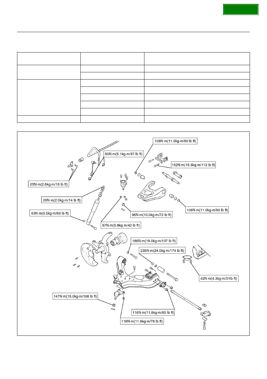
Torque Specifications

450R100007

Front suspension

Type

Independent wishbone arms, torsion bar spring 

with stabilizer bar.

Torsion bar spring

Length

1142mm (45.0in)

Diameter

28.0 mm (1.10 in)

Front shock absorber

Type

Hydraulic, double acting, telescopic

Piston diameter

30.0mm (1.18in)

Stroke

125.0mm (4.92in)

Compressed length

255.0mm (10.04in)

Extended length

380.0mm (14.96in)

Stabilizer bar

Diameter

24.0 mm (0.94 in)

SECTION

FRONT SUSPENSION

3C–27

Special Tools

ILLUSTRATION

TOOL NO.

TOOL NAME

5–8840–2000–0

(J–23907)

Remover;Needle bearing

5–8840–0019–0

Sliding hammer

5–8840–2128–0

(J–36838)

Installer; Needle bearing

5–8840–0007–0

(J–8092)

Grip

5–8840–2127–0

(J–36837)

Installer; Oil seal

5–8840–2307–0

(J–39376)

Installer; Upper arm 

bushing

5–8840–0256–0

(J–29775)

Remover and Installer

Upper arm bushing

5–8840–2123–0

(J–36833)

Remover and Installer kit;

Lower arm front bushing

5–8840–2124–0

(J–36834)

Remover and Installer kit; 

Lower arm rear bushing

5–8840–2121–0

(J–36831)

Ball joint remover

5–8840–2005–0

(J–29107)

Tie-rod end remover

ILLUSTRATION

TOOL NO.

TOOL NAME

SECTION

REAR SUSPENSION

3D–1

FRONTERA

SUSPENSION

REAR SUSPENSION

CONTENTS

Service Precaution......................................... 3D- 1
General Description ....................................... 3D- 1

Diagnosis .................................................... 3D- 2

Coil Spring..................................................... 3D- 5

Coil Spring and Associated Parts ............... 3D- 5
Removal ..................................................... 3D- 5
Inspection and Repair................................. 3D- 6
Installation .................................................. 3D- 6

Shock Absorber............................................. 3D- 7

Shock Absorber and Associated Parts ....... 3D- 7
Removal ..................................................... 3D- 7
Inspection and Repair................................. 3D- 7
Installation .................................................. 3D- 7

Trailing Link................................................... 3D- 8

Trailing Link and Associated Parts ............. 3D- 8
Removal ..................................................... 3D- 8
Inspection and Repair................................. 3D- 8
Installation .................................................. 3D- 9

Upper Link ..................................................... 3D- 10

Upper Link and Associated Parts ............... 3D- 10
Removal...................................................... 3D- 10
Inspection and Repair................................. 3D- 10
Installation................................................... 3D- 11

Lateral Rod.................................................... 3D- 12

Lateral Rod and Associated Parts .............. 3D- 12
Removal...................................................... 3D- 12
Inspection and Repair................................. 3D- 12
Installation................................................... 3D- 13

Stabilizer Bar ................................................. 3D- 14

Stabilizer Bar and Associated Parts ........... 3D- 14
Removal...................................................... 3D- 14
Inspection and Repair................................. 3D- 14
Installation................................................... 3D- 15

Main Data and Specifications ........................ 3D- 16
Special Tools ................................................. 3D- 18

Service Precaution

WARNING:  THIS VEHICLE HAS A SUPPLEMENTAL
RESTRAINT SYSTEM (SRS).   REFER TO 

THE SRS

COMPONENT AND WIRING LOCATION VIEW IN
ORDER TO DETERMINE WHETHER  YOU ARE
PERFORMING SERVICE ON OR NEAR THE SRS
COMPONENTS OR THE SRS WIRING

.  WHEN YOU

ARE PERFORMING SERVICE ON OR NEAR THE
SRS COMPONENTS OR THE SRS WIRING,  REFER
TO THE SRS SERVICE INFORMATION. FAILURE TO
FOLLOW WARNINGS COULD RESULT  IN
POSSIBLE AIR BAG DEPLOYMENT, PERSONAL
INJURY, OR OTHERWISE UNNEEDED SRS SYSTEM
REPAIRS.

CAUTION:  Always use the correct fastener in the
proper location.  When you replace a fastener, use
ONLY the exact part number for that application.
ISUZU will  call out those fasteners that require a
replacement after removal. ISUZU will also call out
the  fasteners that require thread lockers or thread
sealant. UNLESS OTHERWISE SPECIFIED, do  not
use supplemental coatings (Paints, greases, or
other corrosion inhibitors) on threaded  fasteners or
fastener joint interfaces. Generally, such coatings
adversely affect the fastener  torque and the joint
clamping force, and may damage the fastener. When
you install fasteners,  use the correct tightening

sequence and specifications. Following these
instructions can help you  avoid damage to parts
and systems.

General Description

The rear suspension is a 5-link, coil spring type
suspension with a stabilizer bar,  consisting of two
trailing links, two upper links, lateral rod, shock
absorber, and stabilizer.   In this suspension, the links
are specially arranged to enable the rear axle to move
freely,  thereby expanding suspension stroke, reducing
friction, and improving lateral rigidity and roll control.
All these result in improved stability, riding comfort, and
rough road maneuverability.
Each link connects the axle housing with the frame
through a runner bushing.   The axle housing is
supported by the trailing links and upper links
longitudinally and by the lateral rod latitudinally.

SECTION

3D–2

REAR SUSPENSION

Diagnosis

Condition

Possible cause

Correction

Vehicle Pulls

Mismatched or uneven tires.

Replace tire.

Tires not adequately inflated.

Adjust tire pressure.

Broken or sagging springs.

Replace spring.

Radial tire lateral force.

Replace tire.

Improper wheel alignment.

Adjust wheel alignment.

Brake dragging in one wheel.

Repair brake.

Loose, bent or broken front or rear 
suspension parts.

Tighten or replace the appropriate 
suspension part(s).

Faulty shock absorbers.

Replace shock absorber.

Parts in power steering valve 
defective.

Replace power steering unit.

Abnormal or Excessive Tire Wear

Sagging or broken spring.

Replace spring.

Tire out of balance.

Balance or replace tire.

Improper wheel alignment.

Check front end alignment.

Faulty shock absorber.

Replace shock absorber.

Hard driving.

Replace tire.

Overloaded vehicle.

Replace tire and reduce load.

Tires not rotated periodically.

Replace or rotate tire.

Worn or loose road wheel bearings.

Replace wheel bearing.

Wobbly wheel or tires.

Replace wheel or tire.

Tires not adequately inflated.

Adjust the pressure.

Wheel Hop

Blister or bump on tire.

Replace tire.

Improper shock absorber operation.

Replace shock absorber.

Shimmy, Shake or Vibration

Tire or wheel out of balance.

Balance wheels or replace tire/or 
wheel.

Loose wheel bearings.

Replace wheel bearing.

Worn steering linkage ball joints.

Replace ball joints.

Worn upper or lower end ball joints.

Replace ball joints.

Excessive wheel runout.

Repair or replace wheel and/or tire.

Blister or bump on tire.

Replace tire.

Excessive loaded radial runout of 
tire/wheel assembly.

Replace tire or wheel.

Improper wheel alignment.

Check wheel alignment.

Loose or worn steering linkage.

Tighten or replace steering linkage.

Loose steering unit.

Tighten steering unit.

Tires not adequately inflated.

Adjust tire pressure.

Loose, bent or broken front or rear 
suspension parts.

Tighten or replace the appropriate 
suspension parts.

Faulty shock absorber.

Replace shock absorber.

Hub bearing preload misadjustment.

Adjust preload.

Parts in power steering valve 
defective.

Replace power steering unit.

SECTION


Content   ..  1274  1275  1276  1277   ..