Opel Frontera UE. Manual - part 1268


  Index      Opel     Opel Frontera UE - service repair manual 1999-2001 year


Search            


Content   ..  1266  1267  1268  1269   ..


Opel Frontera UE. Manual - part 1268


2A–44

POWER-ASSISTED STEERING SYSTEM

Steering Column

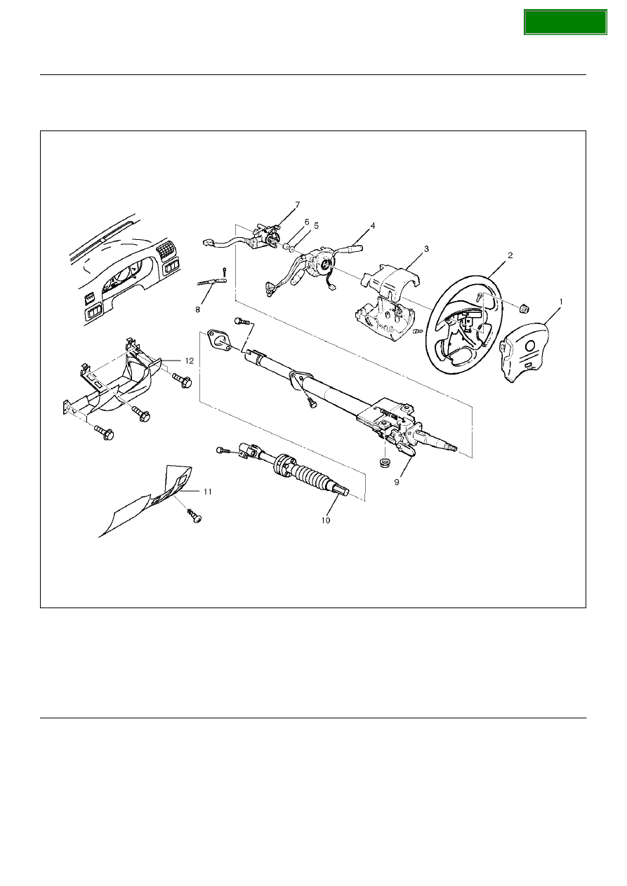
Steering Column and Associated Parts

431RW029

Legend

EndOFCallout

Removal

1. Turn the steering wheel so that the vehicle's wheels 

are pointing straight ahead.

2. Turn the ignition switch to “LOCK".

3. Disconnect the battery “–" terminal cable, and wait 

at least 5 minutes.

4. Disconnect the yellow 2-way SRS connector located 

under the steering column.

CAUTION:  The wheel of the vehicle must be straight 
ahead and the steering column in the “LOCK" 
position before disconnecting the steering column 
from the steering gear.  Failure to do so will cause 
the SRS coil assembly to become uncentered which 
will cause damage to the SRS coil assembly.

(1) Inflator Module
(2) Steering Wheel
(3) Steering Column Cover
(4) Combination Switch and SRS Coil Assembly
(5) Snap Ring
(6) Cushion Rubber

(7) Lock Cylinder Assembly
(8) Shift Lock Cable (For A/T)
(9) Steering Column Assembly

(10) Second Steering Shaft
(11) Instrument Panel Lower Cover
(12) Driver Knee Bolster (reinforcement)

SECTION

POWER-ASSISTED STEERING SYSTEM

2A–45

5. Remove the engine hood opening lever, then 

remove instrument panel lower cover.

6. Remove driver knee bolster (reinforcement).

7. Loosen the inflator module fixing bolt from behind 

the steering wheel assembly using a TORX® driver 
or equivalent until the inflator module can be 
released from steering assembly.

827RW070

8. Disconnect the yellow 2-way SRS connector and 

horn lead located behind the inflator module.

9. Remove inflator module. 

WARNING:  THE INFLATOR MODULE SHOULD 
ALWAYS BE CARRIED WITH THE URETHANE 
COVER AWAY FROM YOUR BODY AND SHOULD 
ALWAYS BE LAID ON A FLAT SURFACE WITH THE 
URETHANE SIDE UP.  THIS IS NECESSARY 
BECAUSE A FREE SPACE IS PROVIDED TO ALLOW 
THE AIR CUSHION TO EXPAND IN THE UNLIKELY 
EVENT OF ACCIDENTAL DEPLOYMENT.  
OTHERWISE, PERSONAL INJURY MAY RESULT.

827RW072

10. Apply a setting mark (1) across the steering wheel 

and shaft so parts can be reassembled in their 
original position. Move the front wheels to the 
straight ahead position,  then use steering wheel 
remover 5–8521–0016–0 to remove the steering 
wheel.   

430RW021

430RX005

11. Remove steering column cover.

12. Disconnect the wiring harness connectors located 

under the steering column.

SECTION

2A–46

POWER-ASSISTED STEERING SYSTEM

13. Remove the combination switch assembly with SRS 

coil.

NOTE:  SRS coil is a part of combination switch 
assembly, which can not be replaced singly.  Therefore, 
be sure not to remove the SRS coil from the 
combination switch assembly.

825RW288

14. Remove snap ring.

15. Remove cushion rubber.

16. Remove shift lock cable (For A/T).

17. Disconnect the starter switch harness connector 

located under the steering column, then remove 
lock cylinder assembly.

18. Apply a setting mark (1) across the universal joint 

and transfer gear to reassemble the parts in their 
original position, then remove steering column 
assembly and second shaft.

NOTE:  A setting mark can be easily made if the shaft is 
withdrawn a little by loosening the steering shaft 
universal joint.

431RW009

SECTION

POWER-ASSISTED STEERING SYSTEM

2A–47

Insepction

If the abnormal conditions are found through inspection, 
replace the steering column assembly.

Column Capsule

Check capsules on steering column bracket assembly; 
all must be securely seated in bracket slots and checked 
for any loose conditions when pushed or pulled by hand.

431RW030

Check clearance between capsule and bracket. If must 
be within 1mm (0.039 in).

431RW031

Column Tube

Check for collapes by measuring the distance as shown 
in the figure.

Standard distance: 162.2-165.8 mm (6.386-6.528 
in)

431RY00010

Column Universal Joint for Tilt Mechanism

If the resistance is felt when checked by rotate the joint, 
replace the steering column assembly.

Sheared Injected Plastic Pin

Check the sheared injected plastic pins for any loose 
conditions or damage.

431RY00011

SECTION


Content   ..  1266  1267  1268  1269   ..