Opel Frontera UE. Manual - part 1250


  Index      Opel     Opel Frontera UE - service repair manual 1999-2001 year


Search            


Content   ..  1248  1249  1250  1251   ..


Opel Frontera UE. Manual - part 1250


HEATING, VENTILATION AND AIR CONDITIONING (HVAC)

1A–121

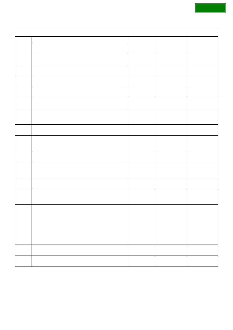
Chart B: Failure on the Intake Control

Step

Action

Value(s)

Yes

No

Is the fuse No.C–15 normal?

Go to Step 2

Replace the 

fuse

Is the fuse No.F–5 normal?

Go to Step 3

Replace the 

fuse

Is the relay No.X–1 normal?

Go to Step 4

Replace the 

relay

Turn on the ignition switch. (the engine is run.)
Is the intake actuator stopped?

Go to Step 6

Go to Step 5

Replace or repair the auto air conditioner control unit.
Is the action complete?

Verify repair

Is there continuity between the harness side
connector terminal No.C65–5 and No.I44–11?

Go to Step 8

Go to Step 7

Repair an open circuit between terminal No.C65–5
and No.I44–11.
Is the action complete?

Go to Step 6

Is there continuity between the harness side
connector terminal No.C65–6 and No.I44–12?

Go to Step 10

Go to Step 9

Repair an open circuit between terminal No.C65–6
and No.I44–12.
Is the action complete?

Go to Step 8

10 

Is there continuity between the harness side
connector terminal No.C65–1 and No.I44–13?

Go to Step 12

Go to Step 11

11 

Repair an open circuit between terminal No.C65–1
and I44-13.
Is the action complete?

Go to Step 10

12 

Is there continuity between the harness side
connector terminal No.C65–2 and No.I44–14?

Go to Step 14

Go to Step 13

13 

Repair an open circuit between harness No.C65–2
and No.I44–14.
Is the action complete?

Go to Step 12

14 

1. Disconnect the intake actuator connector No.C–

65.

2. Is the battery voltage applied between harness

side connector terminal
No.C65–6 and ground?
No.C65–2 and ground?
No.C65–1 and ground?


Go to Step 15

Go to Step 16

15 

Replace or repair the intake actuator.
Is the action complete?

Verify repair

16 

Replace or repair the air conditioner control unit.
Is the action complete?

Verify repair

SECTION

1A–122

HEATING, VENTILATION AND AIR CONDITIONING (HVAC)

Inspection of the Mix Actuator System

D08RX229

Condition

Possible cause

Correction

Does not work at all

Refer to Chart A

Control failure

Refer to Chart B

SECTION

HEATING, VENTILATION AND AIR CONDITIONING (HVAC)

1A–123

Chart A: Does Not work At All

Step

Action

Value(s)

Yes

No

1. Turn on the ignition switch (the engine is run).

2. Disconnect the mix actuator connector (C–45).

3. Short-circuit the chassis harness side connector

terminal No.C45–2 and No.C45–7.

4. Using the temperature control lever, select FH for

the temperature.

Is the battery voltage applied on a regular interval
basis between the harness side connector terminal
No.C45–8 (-) and No.C45–6 (+)?

Go to Step 3

Go to Step 2

Replace the auto air conditioner control unit.


Varify  repair

Using the temperature control lever, select FC for the
temperature.
Is the battery voltage applied on a regular interval
basis between the harness side connector terminal
No.C45–8 (+) and No.C45–6 (-)?

Go to Step 5

Go to Step 4

Replace the auto air conditioner control unit.
  

Verify repair

Is there continuity between the harness side
connector terminal No.I20–6 and No.C45–8?

Go to Step 7

Go to Step 6

Repair an open circuit between terminal No.I20–6 and
No.C45–8.
Is the action complete?

Go to Step 5

Is there continuity between the harness side
connector terminal No.I20–5 and No.C45–6?

Go to Step 9

Go to Step 8

Repair an open circuit between terminal No.I20–5 and
No.C45–6.
Is the action complete?

Go to Step 7

Replace the mix actuator.
Is the action complete?

Verify repair

SECTION

1A–124

HEATING, VENTILATION AND AIR CONDITIONING (HVAC)

Chart B: Mix Actuator Control Failure

Step

Action

Value(s)

Yes

No

Turn the ignition switch (the engine is run).
Does the mix actuator fully stroke when FH and FC of
the temperature control lever?

Go to Step 3

Go to Step 2

Repair or replace the air mix door or the link unit.
Is the action complete?

Varify repair

Is there continuity between the harness side
connector terminal No.C45–2 and No.I44–11?

Go to Step 5

Go to Step 4

Repair an open circuit between terminal No.C45–2
and No.I44–11.
Is the action complete?

Go to Step 3

Is there continuity between harness side connector
terminal No.C45–7 and No.I44–5?

Go to Step 7

Go to Step 6

Repair an open circuit between terminal No.C45–7
and No.I44–5.
Is the action complete?

Go to Step 5

Is there continuity between the harness side
connector terminal No.C45–3 and No.I44–15?

Go to Step 9

Go to Step 8

Repair an open circuit between terminal No.C45–3
and No.I44–15.
Is the action complete?

Go to Step 7

Is sum of the voltage between the following chassis
harness side connector terminals approximately 5V?
No.I44–15 and No.I52–5, No.I44–5 and No.I44–11

Go to Step 11

Go to Step 10

10 

Replace the actuator.
Is the action complete?

Go to Step 9

11 

Replace the auto air conditioner control unit.
Is the action complete?

Verify repair

SECTION


Content   ..  1248  1249  1250  1251   ..