Opel Frontera UE. Manual - part 111


  Index      Opel     Opel Frontera UE - service repair manual 1999-2001 year


Search            


Content   ..  109  110  111  112   ..


Opel Frontera UE. Manual - part 111


TRANSFER CASE

4D–31

Front Output Shaft Oil Seal Replacement

1. Remove the oil seal from the transfer case.
2. Apply engine oil to the oil seal outer surfaces.
3. Apply recommended grease (BESCO L2) or

equivalent to the oil seal lip.

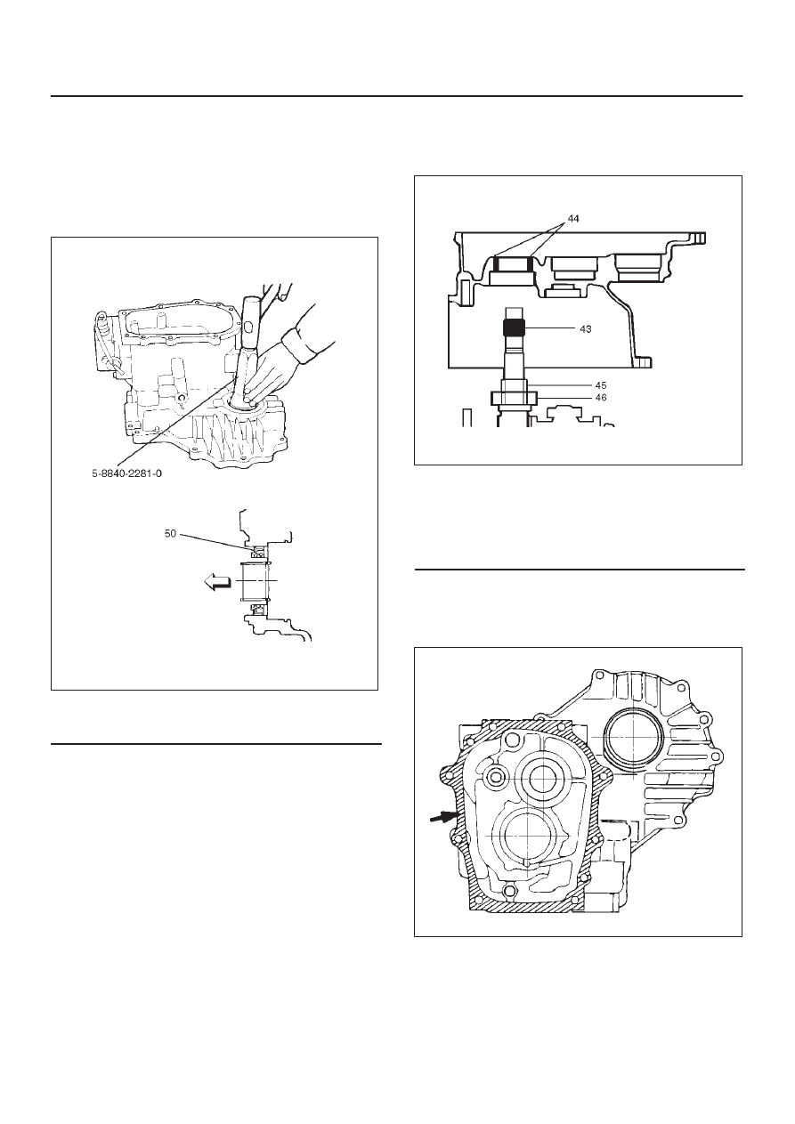
4. Use the oil seal installer 5–8840–2281–0 to install the

oil seal to the transfer case.

220RW131

Legend

(50) Front Output Shaft Oil Seal

1. Install the transfer case (with oil seal) (42), performing

the following steps. (M/T)

D

Cover the shaft splines with adhesive tape (43).
This will prevent damage to the oil seal lip (44).

A07RW022

Legend

(43) Adhesive Tape
(44) Oil Seal Lip
(45) Oil Seal Collar
(46) Bearing

D

Apply recommended liquid gasket (LOCTITE
17430) or its equivalent to the transmission,
intermediate plate and transfer case fitting surfaces
(M/T).

220RS026

4D–32

TRANSFER CASE

Install the transfer case together with intermediate plate
with gear assembly to transmission case (M/T).

Tighten the transfer case bolts to the specified torque a
little at a time (M/T).

Torque : 37 N·m (3.8 kg·m/27 lb ft)

2. Apply chassis grease (51) to the sub–gear (40) and

the counter gear (41) thrust surfaces.

226RW155

3. Install sub–gear (40) to counter gear (41).
4. Install belleville spring (39).
5. Install spacer.
6. Install ball bearing, using a bench press.
7. Select a snap ring that will allow the minimum axial

play.

Clearance : 0–0.1 mm (0–0.004 in)

Snap ring availability:

Thickness

Color–coding

1.50 mm (0.059 in)

White

1.55 mm (0.061 in)

Yellow

1.60 mm (0.063 in)

Blue

226RS170

226RS021

8. Use a pair of snap ring pliers to install the snap ring

(36) to the counter gear (41).

Sub–Gear (anti–lash plate) Preload

1. Hook a length of piano wire (52) over one of the

sub–gear (53) teeth.

2. Attach the other end of the piano wire (52) to a

spring balancer.

3. Measure the sub–gear preload.

Preload : 59–98 N (6.0–10 kg/13–22 lb)

TRANSFER CASE

4D–33

226RW156

9. Install ball bearing (35), using a bench press.

10. Install snap ring (34).

11. Install the counter gear assembly (33) to the transfer

case (42).

12. Use a pair of snap ring pliers to install the snap ring

(32) to the transfer case (42).

NOTE: The snap ring must be fully inserted into the
transfer case snap ring groove.

13. Use a bench press to install the ball bearing (30) to the

front output shaft (31).

262RS012

14. Assemble the 2WD–4WD clutch hub and sleeve

assembly (28).

226RW140

15. Engage the springs in the same insert with the open

ends away from each other.

226RW141

4D–34

TRANSFER CASE

16. Install a new stopper plate (29) and the clutch hub and

sleeve assembly (28) to the front output shaft (31).

226RW157

Legend

(54) Front Output Gear

17. The clutch hub face (with the heavy boss) must be

facing the front output gear side.

18. Use a bench press to slowly force the clutch hub and

sleeve assembly (28) together with the stopper plate
(29) into place.

19. Align the inserts with the block ring insert grooves.

Install the block ring (27) to the clutch sleeve and hub
assembly (28).

20. Install the outside ring (26), inside ring (25) and

needle bearing (24) to the front output gear (23) and
bearing collar (18).

NOTE: Coat all parts with transmission oil before
installing them.

226RW139

21. Apply engine oil to the thrust surfaces of the

sub–gear, the belleville spring, and the spacer (M/T).

262RW014

22. Install sub–gear (anti–lash plate) (22), belleville

spring (21) and spacer (20). (M/T)

23. Install sub–gear snap ring (19). (M/T)
24. Use a bench press to install the needle bearing collar

together with the front output gear assembly, aligning
inside ring claw with block ring groove.

262RS014


Content   ..  109  110  111  112   ..