Content .. 1095 1096 1097 1098 ..
Nissan Frontier D40. Manual - part 1097
TM-286
< ON-VEHICLE REPAIR >
[5AT: RE5R05A]
CONTROL VALVE WITH TCM
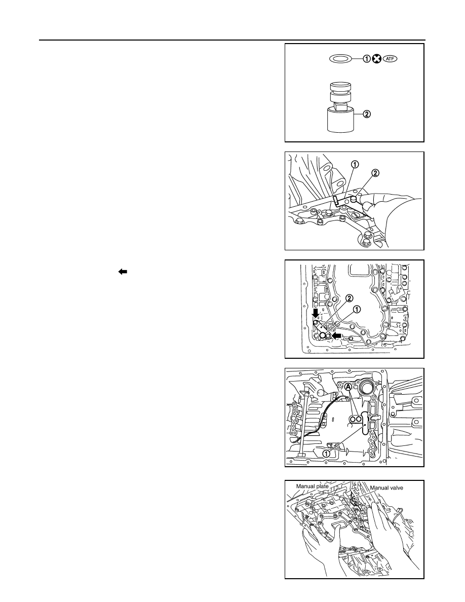
i.
Install new O-ring (1) in plug (2).
CAUTION:
• Do not reuse O-ring.
• Apply ATF to O-ring.
• O-ring should be free of contamination.
ii.
Install plug (2) to bracket (1).
iii.
Install plug (1) [with bracket (2)] to control valve with TCM.
Tighten plug bolt (
) to the specified torque.
CAUTION:
Adjust bolt hole of bracket to bolt hole of control valve with
TCM.
6.
Install control valve with TCM in transmission case.
CAUTION:
• Make sure that input speed sensor is securely installed
into input speed sensor hole (A).
• Hang down output speed sensor harness toward outside
so as not to disturb installation of control valve with TCM.
• Adjust A/T assembly harness connector of control valve
with TCM to terminal hole of transmission case.
• Assemble it so that manual valve cutout is engaged with
manual plate projection.
JSDIA1313ZZ
JSDIA1312ZZ
JSDIA1311ZZ
1
: Brake band
JSDIA1318ZZ
SCIA5142E