Nissan Terrano model r20 series 2004. Manual - part 215
F
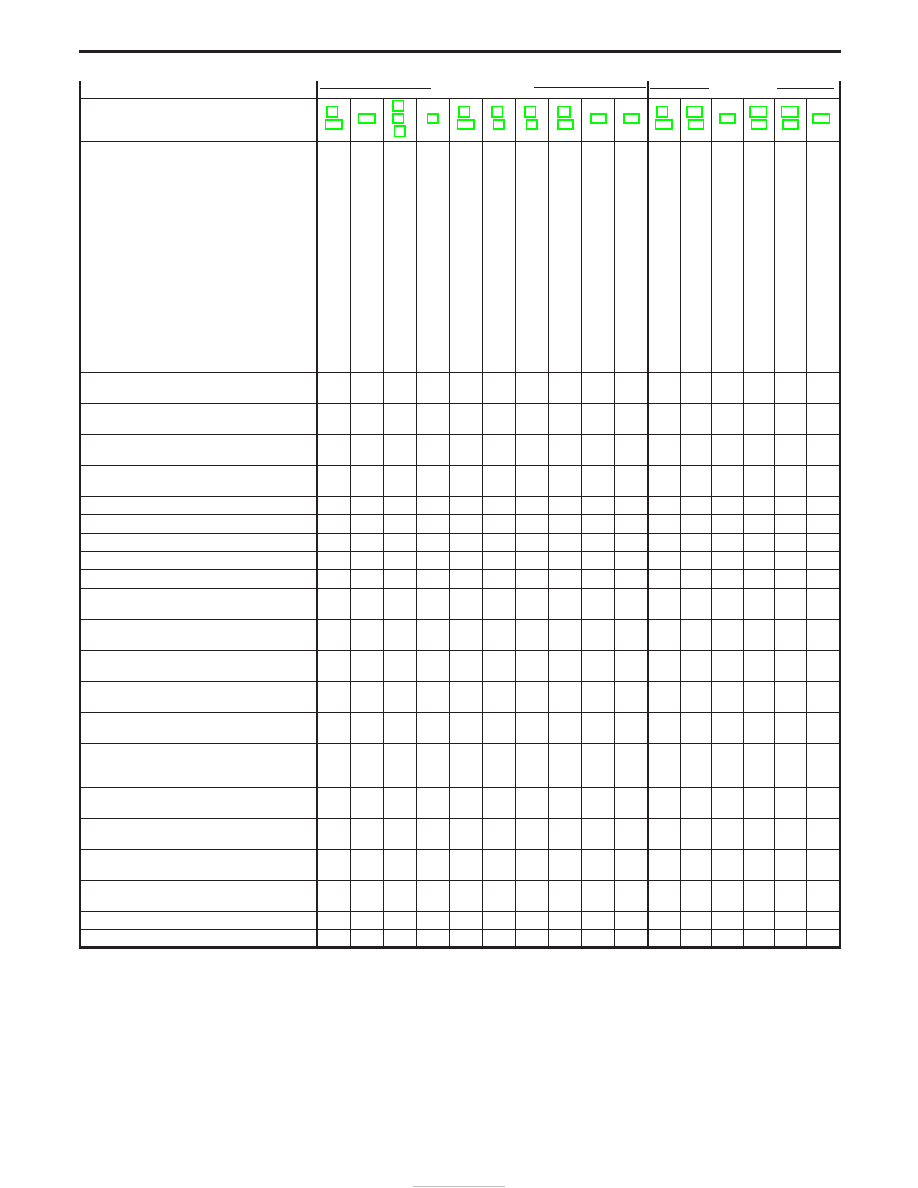
ON vehicle
E F
OFF vehicle
E
Reference page (AT-
)
Numbers are arranged in order of probability.
Perform inspections starting with number one and
work up. Circled numbers indicate that the transmis-
sion must be removed from the vehicle.
Fluid
level
Control
linkage
Park/neutral
position
switch
Throttle
(accelerator)
position
sensor
(Adjustment)
Revolution
sensor
and
vehicle
speed
sensor
Engine
speed
signal
Engine
idling
speed
Line
pressure
Control
valve
assembly
Shift
solenoid
valve
A
Shift
solenoid
valve
B
Line
pressure
solenoid
valve
T
orque
converter
clutch
solenoid
valve
Overrun
clutch
solenoid
valve
A/T
fluid
temperature
sensor
Accumulator
N-D
Accumulator
1-2
Accumulator
2-3
Accumulator
3-4
(N-R)
Ignition
switch
and
starter
T
orque
converter
Oil
pump
Reverse
clutch
High
clutch
Forward
clutch
Forward
one-way
clutch
Overrun
clutch
Low
one-way
clutch
Low
&
reverse
brake
Brake
band
Parking
pawl
components
Too sharp a shock in change from
“D
3
” to “D
4
”.
.
.
.
1
.
.
.
2
4
.
.
.
.
.
.
.
.
.
3
.
.
.
.
.
.
.
q
6
.
.
q
5
.
Almost no shock or clutches slipping in change from
“D
1
” to “D
2
”.
1
.
.
2
.
.
.
3
5
.
.
.
.
.
.
.
4
.
.
.
.
.
.
.
.
.
.
.
.
q
6
.
Almost no shock or slipping in change from “D
2
” to
“D
3
”.
1
.
.
2
.
.
.
3
5
.
.
.
.
.
.
.
.
4
.
.
.
.
.
q
6
.
.
.
.
.
q
7
.
Almost no shock or slipping in change from “D
3
” to
“D
4
”.
1
.
.
2
.
.
.
3
5
.
.
.
.
.
.
.
.
.
4
.
.
.
.
q
6
.
.
.
.
.
q
7
.
Vehicle braked by gear change from “D
1
” to “D
2
”.
1
.
.
.
.
.
.
.
.
.
.
.
.
.
.
.
.
.
.
.
.
.
q
2
q
4
.
.
.
q
5
q
3
.
.
Vehicle braked by gear change from “D
2
” to “D
3
”.
1
.
.
.
.
.
.
.
.
.
.
.
.
.
.
.
.
.
.
.
.
.
.
.
.
.
.
.
.
q
2
.
Vehicle braked by gear change from “D
3
” to “D
4
”.
1
.
.
.
.
.
.
.
.
.
.
.
.
.
.
.
.
.
.
.
.
.
q
4
.
.
q
3
q
2
.
.
.
.
Maximum speed not attained. Acceleration poor.
1
.
2
.
.
.
.
.
5
3
4
.
.
.
.
.
.
.
.
.
q
11
q
10
q
6
q
7
.
.
.
.
q
9
q
8
.
Failure to change gear from “D
4
” to “D
3
”.
1
.
.
2
.
.
.
.
6
4
.
5
.
3
.
.
.
.
.
.
.
.
.
.
.
.
q
8
.
q
7
.
.
Failure to change gear from “D
3
” to “D
2
” or from
“D
4
” to “D
2
”.
1
.
.
2
.
.
.
.
5
3
4
.
.
.
.
.
.
.
.
.
.
.
.
q
6
.
.
.
.
.
q
7
.
Failure to change gear from “D
2
” to “D
1
” or from
“D
3
” to “D
1
”.
1
.
.
2
.
.
.
.
5
3
4
.
.
.
.
.
.
.
.
.
.
.
.
q
7
.
.
.
q
6
.
q
8
.
Gear change shock felt during deceleration by
releasing accelerator pedal.
.
.
.
1
.
.
.
2
4
.
.
.
.
3
.
.
.
.
.
.
.
.
.
.
.
.
.
.
.
.
.
Too high a change point from “D
4
” to “D
3
”, from “D
3
”
to “D
2
”, from “D
2
” to “D
1
”.
.
.
.
1
2
.
.
.
.
.
.
.
.
.
.
.
.
.
.
.
.
.
.
.
.
.
.
.
.
.
.
Kickdown does not operate when depressing pedal
in “D
4
” within kickdown vehicle speed.
.
.
.
1
2
.
.
.
.
3
4
.
.
.
.
.
.
.
.
.
.
.
.
.
.
.
.
.
.
.
.
Kickdown operates or engine overruns when
depressing pedal in “D
4
” beyond kickdown vehicle
speed limit.
.
.
.
2
1
.
.
.
.
3
4
.
.
.
.
.
.
.
.
.
.
.
.
.
.
.
.
.
.
.
.
Races extremely fast or slips in changing from “D
4
”
to “D
3
” when depressing pedal.
1
.
.
2
.
.
.
3
5
.
.
4
.
.
.
.
.
.
.
.
.
.
.
q
6
q
7
.
.
.
.
.
.
Races extremely fast or slips in changing from “D
4
”
to “D
2
” when depressing pedal.
1
.
.
2
.
.
.
3
6
5
.
4
.
.
.
.
.
.
.
.
.
.
.
.
q
8
.
.
.
.
q
7
.
Races extremely fast or slips in changing from “D
3
”
to “D
2
” when depressing pedal.
1
.
.
2
.
.
.
3
5
.
.
4
.
.
6
.
.
7
.
.
.
.
.
q
10
q
9
.
.
.
.
q
8
.
Races extremely fast or slips in changing from “D
4
”
or “D
3
” to “D
1
” when depressing pedal.
1
.
.
2
.
.
.
3
5
.
.
4
.
.
.
.
.
.
.
.
.
.
.
.
q
6
q
7
.
q
8
.
.
.
Vehicle will not run in any position.
1
2
.
.
.
.
.
3
.
.
.
4
.
.
.
.
.
.
.
.
q
9
q
5
.
q
6
.
.
.
.
q
8
q
7
q
10
Transmission noise in “D”, “2”, “1” and “R” positions. 1
.
.
.
.
.
.
.
.
.
.
.
.
.
.
.
.
.
.
.
q
2
.
.
.
.
.
.
.
.
.
.
TROUBLE DIAGNOSIS — General Description
Symptom Chart (Cont’d)
AT-44