Nissan Titan A60. Manual - part 422


  Index      Nissan     Nissan Titan A60 (2011 year) - Service and Repair Manual


Search            


Content   ..  420  421  422  423   ..


Nissan Titan A60. Manual - part 422


EC-354

< DTC/CIRCUIT DIAGNOSIS >

[VK56DE]

P1140, P1145 IVT CONTROL POSITION SENSOR

>> INSPECTION END

Component Inspection

INFOID:0000000006158805

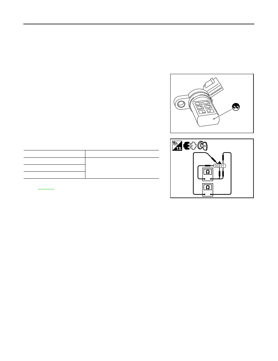
INTAKE VALVE TIMING CONTROL POSITION SENSOR

1. Disconnect intake valve timing control position sensor harness connector.
2. Loosen the fixing bolt of the sensor.
3. Remove the sensor.
4. Visually check the sensor for chipping.

5. Check resistance as shown below.

6. If NG, replace intake valve timing control position sensor. Refer

to 

EC-478

.

SEF362Z

Terminal No. (Polarity)

Resistance 

Ω [at 25°C (77°F)]

3 (+) - 1 (-)

Except 0 or 

2 (+) - 1 (-)

3 (+) - 2 (-)

JMBIA0600ZZ

P1148, P1168 CLOSED LOOP CONTROL

EC-355

< DTC/CIRCUIT DIAGNOSIS >

[VK56DE]

C

D

E

F

G

H

I

J

K

L

M

A

EC

N

P

O

P1148, P1168 CLOSED LOOP CONTROL

On Board Diagnosis Logic

INFOID:0000000006158806

These self-diagnoses have the one trip detection logic.

DTC P1148 or P1168 is displayed with another DTC for air fuel ratio (A/F) sensor 1.

Perform the trouble diagnosis for the corresponding DTC.

DTC No.

Trouble diagnosis name

DTC detecting condition

Possible cause

P1148
1148
(Bank 1)

Closed loop control 
function

The closed loop control function for bank 1 does 
not operate even when vehicle is driving in the 
specified condition.

• Harness or connectors

[The air fuel ratio (A/F) sensor 1 circuit is 
open or shorted.]

• Air fuel ratio (A/F) sensor 1
• Air fuel ratio (A/F) sensor 1 heater

P1168
1168
(Bank 2)

The closed loop control function for bank 2 does 
not operate even when vehicle is driving in the 
specified condition.

EC-356

< DTC/CIRCUIT DIAGNOSIS >

[VK56DE]

P1211 TCS CONTROL UNIT

P1211 TCS CONTROL UNIT

Description

INFOID:0000000006158807

The malfunction information related to TCS is transferred through the CAN communication line from “ABS

actuator and electric unit (control unit)” to ECM.

Be sure to erase the malfunction information such as DTC not only for “ABS actuator and electric unit

(control unit)” but also for ECM after TCS related repair.

On Board Diagnosis Logic

INFOID:0000000006158808

Freeze frame data is not stored in the ECM for this self-diagnosis.

The MIL will not light up for this self-diagnosis.

DTC Confirmation Procedure

INFOID:0000000006158809

TESTING CONDITION:

Before performing the following procedure, confirm that battery voltage is more than 10.5V at idle.
1. Start engine and let it idle for at least 60 seconds.
2. Check 1st trip DTC.
3. If 1st trip DTC is detected, go to 

EC-356, "Diagnosis Procedure"

.

Diagnosis Procedure

INFOID:0000000006158810

Go to 

BRC-24, "CONSULT-III Function (ABS)"

.

DTC No.

Trouble diagnosis name

DTC detecting condition

Possible cause

P1211
1211

TCS control unit

ECM receives a malfunction information from
“ABS actuator electric unit (control unit)”

• ABS actuator and electric unit (control 

unit)

• TCS related parts

P1212 TCS COMMUNICATION LINE

EC-357

< DTC/CIRCUIT DIAGNOSIS >

[VK56DE]

C

D

E

F

G

H

I

J

K

L

M

A

EC

N

P

O

P1212 TCS COMMUNICATION LINE

Description

INFOID:0000000006158811

NOTE:

• If DTC P1212 is displayed with DTC U0101 or U1001, first perform the trouble diagnosis for DTC

U0101, U1001. Refer to 

EC-140

.

• If DTC P1212 is displayed with DTC P0607, first perform the trouble diagnosis for DTC P0607. Refer

to 

EC-344

.

This CAN communication line is used to control the smooth engine operation during the TCS operation. Pulse

signals are exchanged between ECM and “ABS actuator and electric unit (control unit)”.

Be sure to erase the malfunction information such as DTC not only for “ABS actuator and electric unit

(control unit)” but also for ECM after TCS related repair.

On Board Diagnosis Logic

INFOID:0000000006158812

Freeze frame data is not stored in the ECM for this self-diagnosis.

The MIL will not light up for this self-diagnosis.

DTC Confirmation Procedure

INFOID:0000000006158813

TESTING CONDITION:

Before performing the following procedure, confirm that battery voltage is more than 10.5V at idle.
1. Start engine and let it idle for at least 10 seconds.
2. Check 1st trip DTC.
3. If 1st trip DTC is detected, go to 

EC-357, "Diagnosis Procedure"

Diagnosis Procedure

INFOID:0000000006158814

Go to 

BRC-24, "CONSULT-III Function (ABS)"

.

DTC No.

Trouble diagnosis name

DTC detecting condition

Possible cause

P1212
1212

TCS communication line

ECM can not receive the information from 
“ABS actuator and electric unit (control 
unit)” continuously.

• Harness or connectors

(The CAN communication line is open or short-
ed.)

• ABS actuator and electric unit (control unit)
• Dead (Weak) battery


Content   ..  420  421  422  423   ..