Nissan Titan A60. Manual - part 46
AV
AUDIO SYSTEM
AV-9
< SYSTEM DESCRIPTION >
[BASE AUDIO]
C
D
E
F
G
H
I
J
K
L
M
B
A
O
P
SYSTEM DESCRIPTION
AUDIO SYSTEM
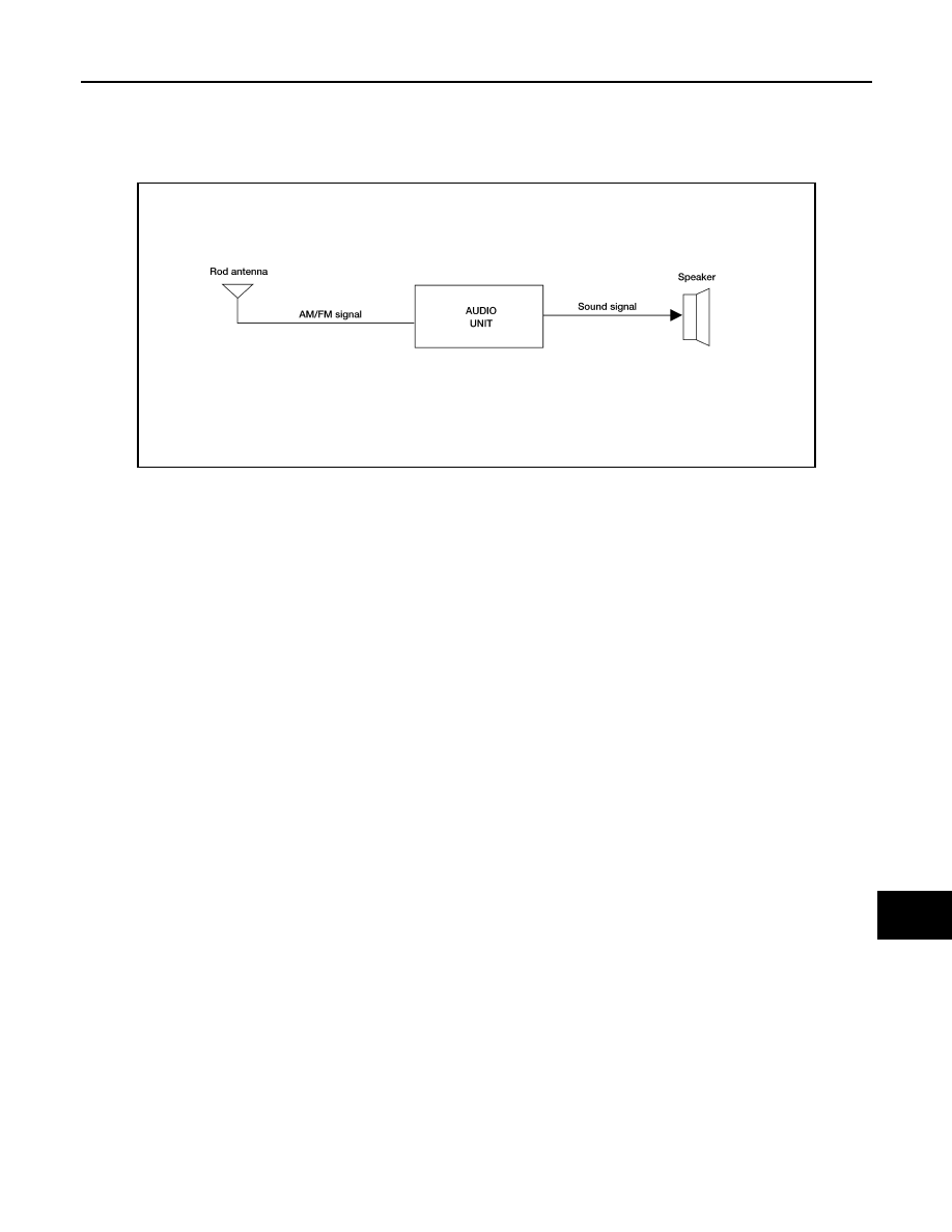
System Diagram
INFOID:0000000006166435
System Description
INFOID:0000000006166436
AUDIO SYSTEM
The audio system consists of the following components
• Audio unit
• Rod antenna
• Front door speakers
• Front tweeters
• Rear door speakers
• Rear door tweeters (crew cab)
When the audio system is on, radio signals are received by the rod antenna. The audio unit then sends audio
signals to the front door speakers, front tweeters, rear door speakers and rear door tweeters (crew cab).
Refer to Owner's Manual for audio system operating instructions.
AWNIA1613GB