Nissan Quest E52. Manual - part 673
FAX-20
< REMOVAL AND INSTALLATION >
FRONT DRIVE SHAFT
6.
Remove cotter pin, and then loosen wheel hub lock nut. Refer to
FAX-9, "Removal and Installation"
.
7.
Patch wheel hub lock nut with a piece of wood. Hammer the
wood to disengage wheel hub assembly from drive shaft.
NOTE:
Use suitable puller, if wheel hub assembly and drive shaft can-
not be separated even after performing the above procedure.
8.
Remove wheel hub lock nut. Refer to
.
9.
Remove strut assembly from steering knuckle. Refer to
10. Remove drive shaft from wheel hub assembly.
CAUTION:
• Never place drive shaft joint at an extreme angle. Also be
careful not to overextend slide joint.
• Never allow drive shaft to hang down without support for joint sub-assembly, shaft and the other
parts.
11. Remove splash guard. Refer to
12. Remove bearing housing mounting bolts.
13. Remove drive shaft assembly from transaxle assembly.
CAUTION:
Never place drive shaft joint at an extreme angle when
removing drive shaft. Also be careful not to overextend
slide joint.
14. Remove heat insulator from front suspension member.
15. Remove front exhaust tube. Refer to
.
16. Remove three way catalyst (bank 1) and heated oxygen sensor
harness bracket. Refer to
EM-33, "Removal and Installation"
17. Remove support bearing bracket.
18. Perform inspection after removal. Refer to
.
INSTALLATION
Note the following, and install in the reverse order of removal.
Transaxle Side
• Always replace transaxle side oil seal with new one when installing drive shaft. Refer to
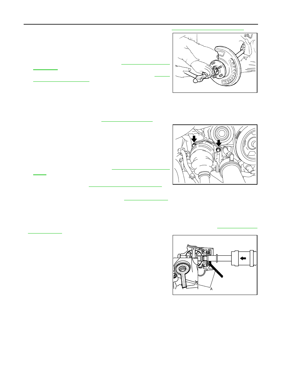
• Place the protector (A) [SST: KV38107900 (
—
)] onto transaxle
assembly to prevent damage to the oil seal while inserting drive
shaft. Slide drive shaft sliding joint and tap with a hammer to install
securely.
• Install support bearing bracket in following procedure.
JPDIG0070ZZ
JSDIA2709ZZ
JPDIF0049ZZ