Nissan Quest E52. Manual - part 501
EC-214
< DTC/CIRCUIT DIAGNOSIS >
[VQ35DE]
P0132, P0152 A/F SENSOR 1
With GST
Follow the procedure “With CONSULT” above.
Is 1st trip DTC detected?
YES
>> Proceed to
.
NO
>> INSPECTION END
Diagnosis Procedure
INFOID:0000000009651072
1.
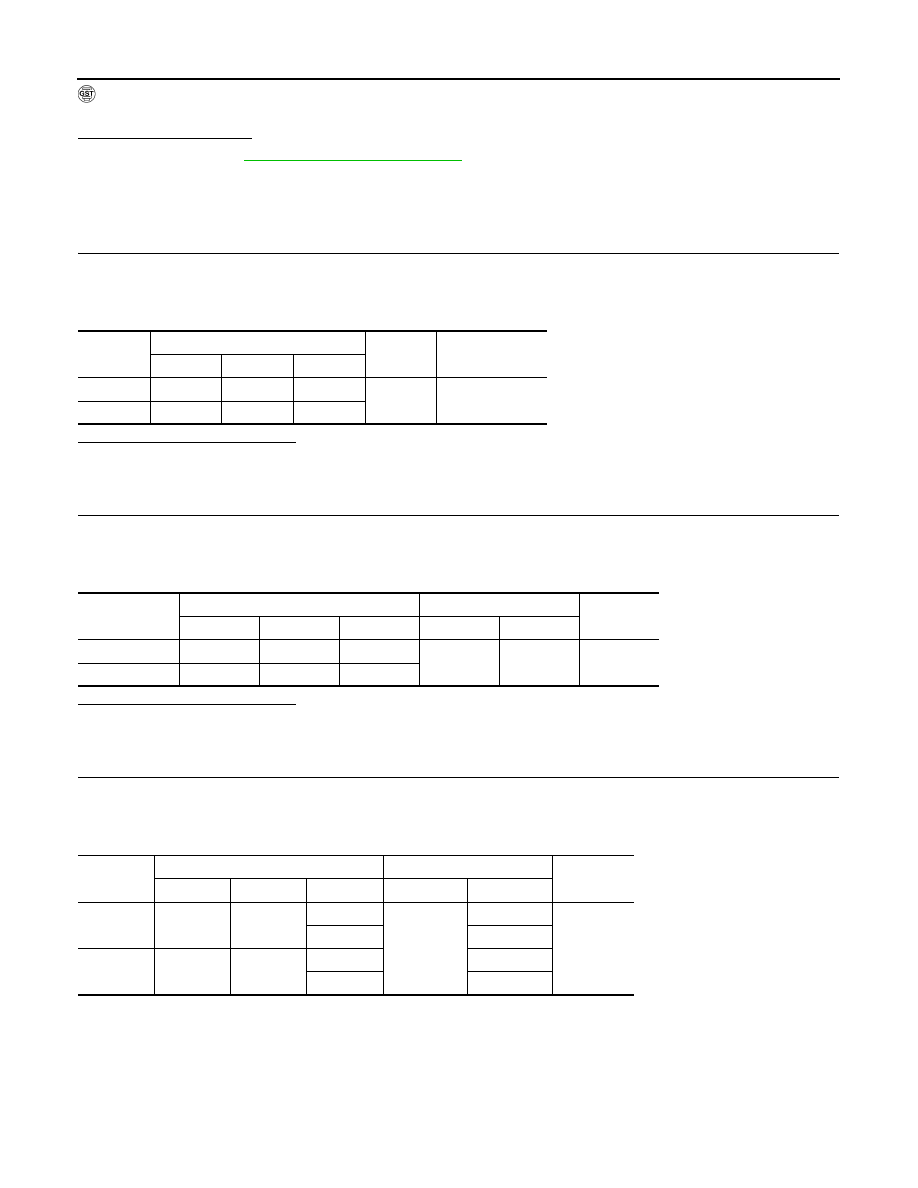
CHECK AIR FUEL RATIO (A/F) SENSOR 1 POWER SUPPLY
1.
Disconnect A/F sensor 1 harness connector.
2.
Turn ignition switch ON.
3.
Check the voltage between A/F sensor 1 harness connector and ground.
Is the inspection result normal?
YES
>> GO TO 3.
NO
>> GO TO 2.
2.
CHECK AIR FUEL RATIO (A/F) SENSOR 1 POWER SUPPLY CIRCUIT
1.
Turn ignition switch OFF.
2.
Disconnect IPDM E/R harness connector.
3.
Check the continuity between A/F sensor 1 harness connector and IPDM E/R harness connector.
Is the inspection result normal?
YES
>> Perform the trouble diagnosis for power supply circuit.
NO
>> Repair or replace error-detected parts.
3.
CHECK A/F SENSOR 1 INPUT SIGNAL CIRCUIT FOR OPEN AND SHORT
1.
Turn ignition switch OFF.
2.
Disconnect ECM harness connector.
3.
Check the continuity between A/F sensor 1 harness connector and ECM harness connector.
4.
Check the continuity between A/F sensor 1 harness connector and ground, or ECM harness connector
and ground.
DTC
A/F sensor 1
Ground
Voltage
Bank
Connector
Terminal
P0132
1
F27
4
Ground
Battery voltage
P0152
2
F64
4
DTC
A/F sensor 1
IPDM E/R
Continuity
Bank
Connector
Terminal
Connector
Terminal
P0132
1
F27
4
F12
57
Existed
P0152
2
F64
4
DTC
A/F sensor 1
ECM
Continuity
Bank
Connector
Terminal
Connector
Terminal
P0132
1
F27
1
F8
69
Existed
2
73
P0152
2
F64
1
77
2
81