Nissan Quest E52. Manual - part 147
AV
DIAGNOSIS SYSTEM (AV CONTROL UNIT)
AV-467
< SYSTEM DESCRIPTION >
[BOSE AUDIO WITH NAVIGATION]
C
D
E
F
G
H
I
J
K
L
M
B
A
O
P
A Connecting Cable Between Units Is Displayed In Yellow.
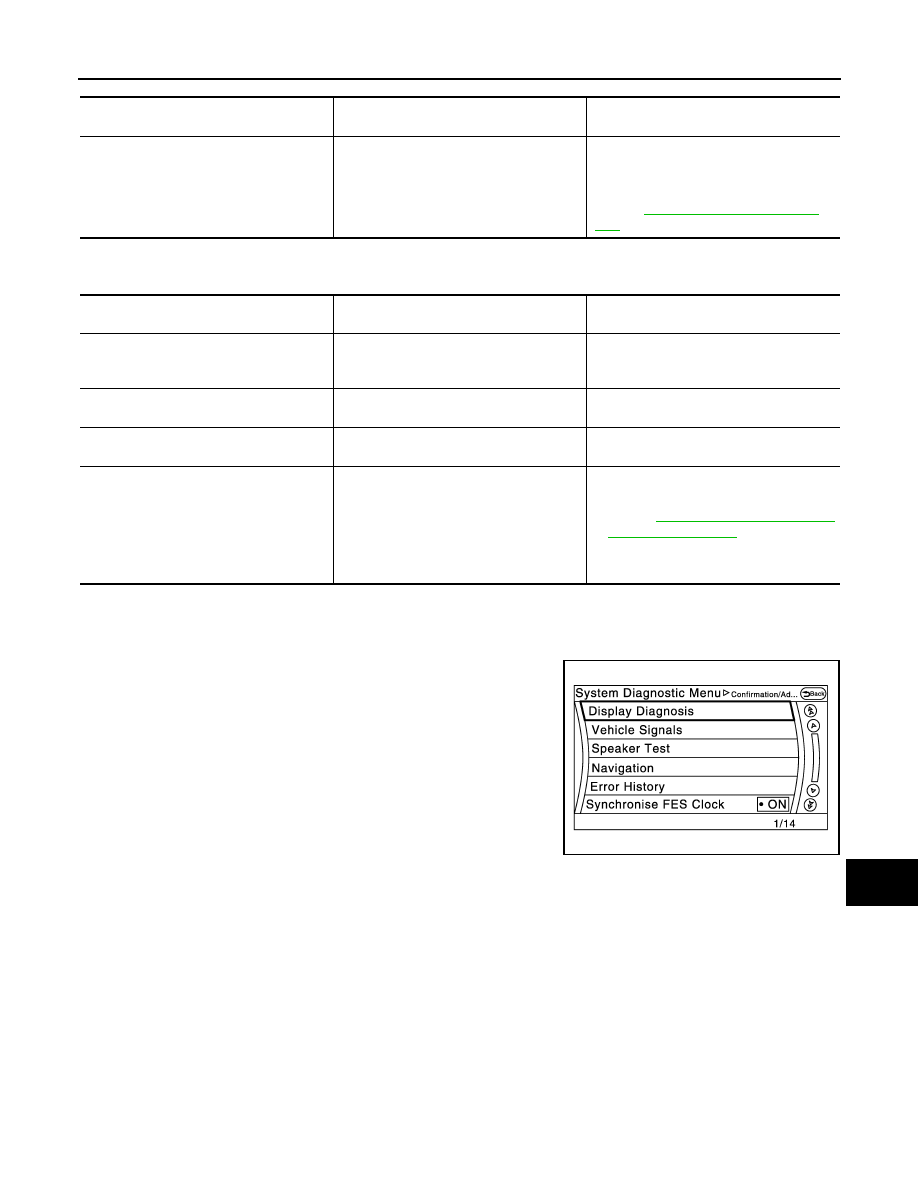
CONFIRMATION/ADJUSTMENT MODE
1.
Start the diagnosis function and select “Confirmation/Adjustment”. The confirmation/adjustment mode
indicates where each item can be checked or adjusted.
2.
Select each switch on the “Confirmation/Adjustment Mode”
screen to display the relevant trouble diagnosis screen. Press
the “Back” switch to return to the initial Confirmation/Adjustment
Mode screen.
Screen switch
Description
Possible malfunction location / Action to
take
Control Unit
Malfunction is detected in AV control unit
power supply and ground circuits.
Check AV control unit power supply and
ground circuits. When detecting no mal-
function in those components, replace AV
control unit.
Refer to
AV-610, "Removal and Installa-
.
Area with yellow connection lines
Description
Possible malfunction location / Action to
take
Control unit
⇔
Front Display
Serial communication circuits between AV
control unit and front display unit are mal-
functioning.
Serial communication circuits between AV
control unit and front display unit.
Control unit
⇔
GPS Antenna
GPS antenna connection malfunctions de-
tected.
GPS antenna
Control unit
⇔
XM Antenna
Satellite radio antenna connection malfunc-
tion is detected.
Satellite radio antenna disconnection
Control unit
⇔
Video Dist.(Rear)
When either one of the following items are
detected:
• Rear display unit power supply and
ground circuits are malfunctioning.
• AV communication circuits between AV
control unit and rear display unit are mal-
functioning.
• Rear display unit power supply and
ground circuits.
Refer to
.
• AV communication circuits between AV
control unit and rear display unit.
JSNIA2483ZZ