Content .. 1196 1197 1198 1199 ..
Nissan Quest E52. Manual - part 1198
TM-22
< SYSTEM DESCRIPTION >
[CVT: RE0F09B]
STRUCTURE AND OPERATION
FLUID COOLER & FLUID WARMER SYSTEM
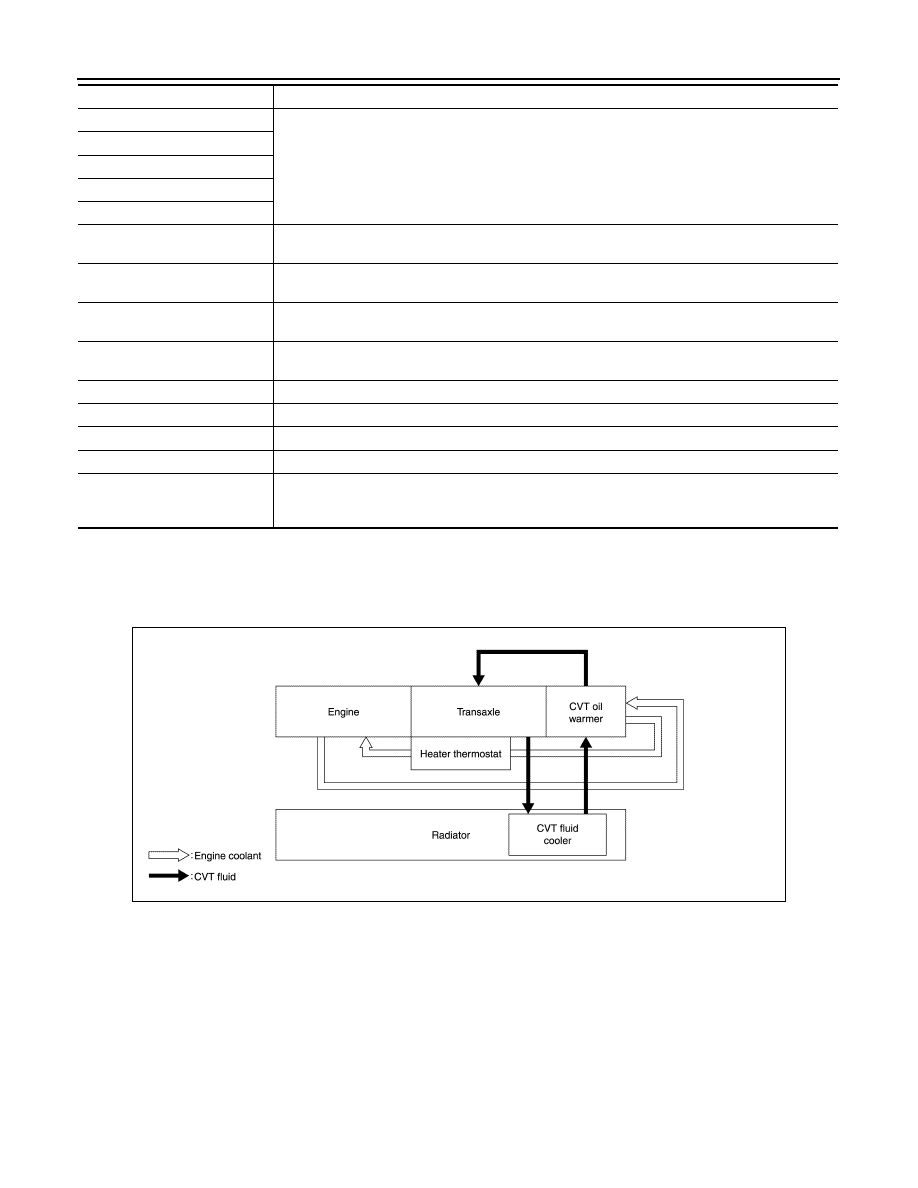
FLUID COOLER & FLUID WARMER SYSTEM : System Description
INFOID:0000000009650083
CVT FLUID COOLER SCHEMATIC
COMPONENT DESCRIPTION
CVT Fluid Cooler
Output gear
The deceleration gears are composed of 2 stages: primary deceleration (output gear, idler gear pair)
and secondary deceleration (reduction gear, final gear pair). All of these gears are helical gears.
Idler gear
Reduction gear
Final gear
Differential
Torque converter regulator valve
Adjusts the feed pressure to the torque converter to the optimum pressure corresponding to the driv-
ing condition.
Pressure regulator valve
Adjusts the discharge pressure from the oil pump to the optimum pressure (line pressure) corre-
sponding to the driving condition.
Torque converter clutch control
valve
Adjusts the torque converter engage and disengage pressures.
Shift control valve
Controls the line pressure that is applied to the primary pulley according to the stroke difference be-
tween the step motor and primary pulley.
Secondary valve
Reduces the line pressure and adjusts the secondary pressure.
Clutch regulator valve
Adjusts the clutch operating pressure according to the driving conditions.
Manual valve
Distributes the clutch operation pressure to each circuit according to the selector lever position.
Select control valve
Engages when selected. Adjusts the forward clutch pressure and reverse brake pressure.
Select switch valve
Performs switching control of the torque converter clutch solenoid valve control pressure when lock
up is engaged/disengaged, and when the forward/reverse clutches (forward clutch and reverse
brake) are engaged/disengaged.
Part name
Function
JSDIA2219GB