Nissan Quest E52. Manual - part 21
RECLINING SENSOR
ADP-77
< DTC/CIRCUIT DIAGNOSIS >
C
D
E
F
G
H
I
K
L
M
A
B
ADP
N
O
P
RECLINING SENSOR
Component Function Check
INFOID:0000000009649668
1.
CHECK FUNCTION
1.
Select “RECLN PULSE” in “Data monitor” mode with CONSULT.
2.
Check reclining sensor signal under the following conditions.
*
: The value at the seat position attained when the battery is connected is considered to be 32768.
Is the indication normal?
YES
>> INSPECTION END
NO
>> Refer to
.
Diagnosis Procedure
INFOID:0000000009649669
1.
CHECK RECLINING SENSOR SIGNAL
1.
Turn ignition switch ON.
2.
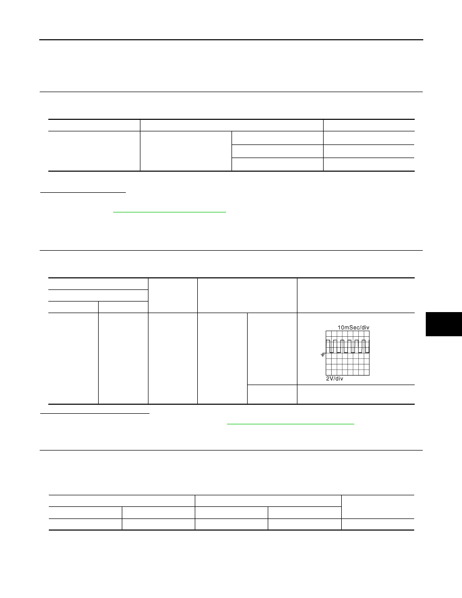
Check signal between driver seat control unit harness connector and ground using an oscilloscope.
Is the inspection result normal?
YES
>> Replace driver seat control unit. Refer to
ADP-111, "Removal and Installation"
NO
>> GO TO 2.
2.
CHECK RECLINING SENSOR CIRCUIT
1.
Turn ignition switch OFF.
2.
Disconnect driver seat control unit connector and reclining motor connector.
3.
Check continuity between driver seat control unit harness connector and reclining motor harness connec-
tor.
4.
Check continuity between driver seat control unit harness connector and ground.
Monitor item
Condition
Value
RECLN PULSE
Seat reclining
Operate (forward)
Change (increase)
*
Operate (backward)
Change (decrease)
*
Release
No change
*
(+)
(-)
Condition
Signal (V)
(Reference value)
Driver seat control unit
Connector
Terminals
B552
4
Ground
Seat reclining
Operate
Other than the
above
0 – 1 or 4 – 6
JMJIA0119ZZ
Driver seat control unit
Reclining motor
Continuity
Connector
Terminal
Connector
Terminal
B552
4
B554
4
Existed