Nissan Cube. Manual - part 940
TM-16
< PREPARATION >
[6MT: RS6F94R]
PREPARATION
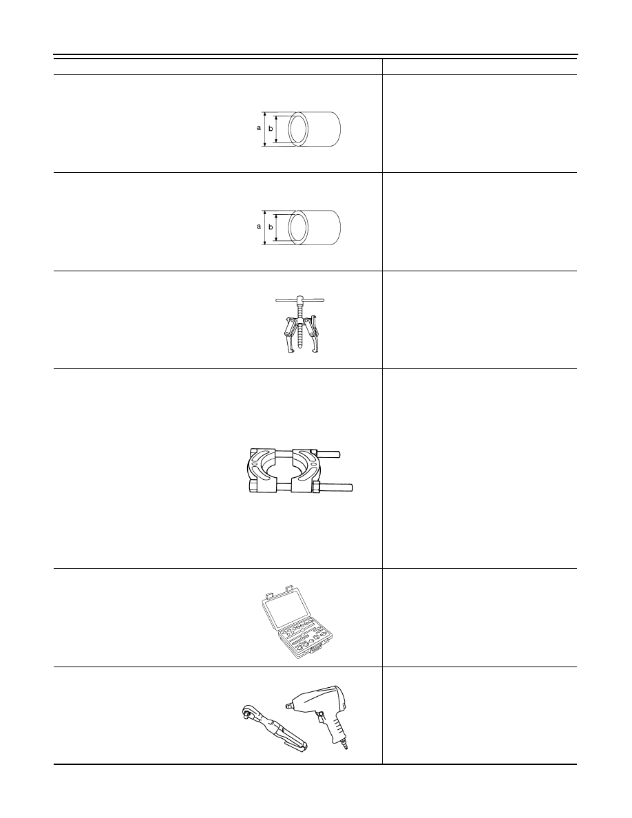
Drift
a: 45 mm (1.77 in) dia.
b: 39 mm (1.54 in) dia.
Installing differential side bearing inner race
(clutch housing side)
Drift
a: 52 mm (2.05 in) dia.
b: 45 mm (1.77 in) dia.
Installing differential side bearing inner race
(transaxle case side)
Puller
• Removing differential side bearing inner
race (clutch housing side)
• Removing differential side bearing inner
race (transaxle case side)
Puller
• Removing differential side bearing inner
race (clutch housing side)
• Removing differential side bearing inner
race (transaxle case side)
• Removing input shaft rear bearing
• Removing input shaft front bearing
• Removing mainshaft rear bearing inner race
• Removing 6th main gear
• Removing 4th main gear
• Removing 5th main gear
• Removing 1st main gear
• Removing 1st-2nd synchronizer hub as-
sembly
• Removing 2nd main gear
• Removing 3rd main gear
• Removing mainshaft front bearing inner
race
Remover
• Removing bushing
• Removing mainshaft rear bearing outer
race
Power tool
Loosening bolts and nuts
Tool name
Description
S-NT474
S-NT474
NT077
ZZB0823D
S-NT134
PBIC0190E