Nissan Cube. Manual - part 915


  Index      Nissan     Nissan Cube (2014 year) - Service and Repair Manual


Search            


Content   ..  913  914  915  916   ..


Nissan Cube. Manual - part 915


ST-2

< SYMPTOM DIAGNOSIS >

NOISE, VIBRATION AND HARSHNESS (NVH) TROUBLESHOOTING

SYMPTOM DIAGNOSIS

NOISE, VIBRATION AND HARSHNESS (NVH) TROUBLESHOOTING

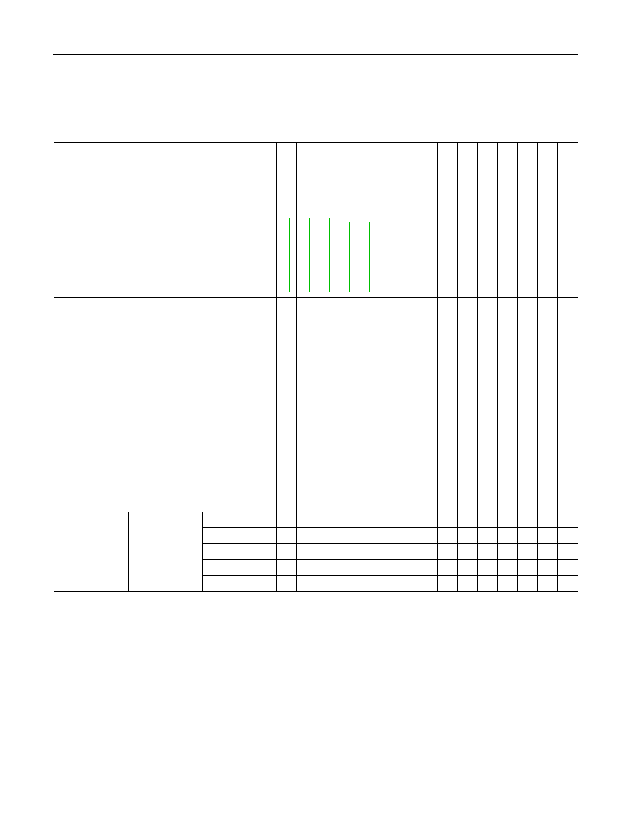
NVH Troubleshooting Chart

INFOID:0000000009949808

Use the chart below to find the cause of the symptom. If necessary, repair or replace these parts.

×

: Applicable

Reference

ST

-18,

 "

In

sp

ectio

n

"

ST

-18,

 "

In

sp

ectio

n

"

ST

-18,

 "

In

sp

ectio

n

"

ST

-7, "

Inspe

c

ti

on

"

ST

-7, "

Inspe

c

ti

on

"

ST

-14,

 "

Ex

pl

od

ed V

iew

"

ST

-12,

 "

In

sp

ectio

n

"

ST

-1

1, "

Ex

pl

od

ed

 V

iew

"

ST

-14,

 "

Ex

pl

od

ed V

iew

"

NVH in F

AX, RAX

, FSU, RSU section

NVH in WT

 se

ct

io

n

NVH in WT

 se

ct

io

n

NVH in F

AX section

NVH in BR section

Possible cause and SUSPECTED PARTS

Oute

r/in

ne

r s

o

c

k

e

t b

a

ll jo

in

t s

w

ing

in

g

 t

o

rq

ue

Oute

r/in

ne

r socke

t b

a

ll jo

in

t ro

ta

ti

ng

 to

rqu

e

Oute

r/in

ne

r s

o

c

k

e

t b

a

ll jo

in

t e

n

d

 pl

ay

S

te

e

ri

ng

 whe

e

l pl

ay

Im

prop

er st

eeri

n

g

 whe

e

l

Im

prop

er 

in

st

a

lla

ti

on

 or l

o

o

s

e

n

e

s

s

 o

f ti

lt 

loc

k

 le

ve

r

M

ou

nt

ing

 l

o

os

en

es

s

S

tee

rin

g

 c

o

lu

m

n

 d

e

fo

rm

at

io

n

 or da

ma

ge

Im

prop

er 

in

st

a

lla

ti

on

 or l

o

o

s

e

n

e

s

s

 o

f s

tee

rin

g

 c

o

lu

m

n

S

tee

rin

g l

inka

ge

 lo

os

en

es

s

AXLE

 and 

SUSPENSION

TIRE

ROA

D

 WHEEL

DRIVE SHA

F

T

BRAKE

Symptom

Steering

Noise

×

×

×

×

×

×

×

×

×

×

×

Shake

×

×

×

×

×

×

×

×

Vibration

×

×

×

×

×

×

×

×

Shimmy

×

×

×

×

×

×

×

Judder

×

×

×

×

×

×

×

PRECAUTIONS

ST-3

< PRECAUTION >

C

D

E

F

H

I

J

K

L

M

A

B

ST

N

O

P

PRECAUTION

PRECAUTIONS

Precaution for Supplemental Restraint System (SRS) "AIR BAG" and "SEAT BELT 
PRE-TENSIONER"

INFOID:0000000009949809

The Supplemental Restraint System such as “AIR BAG” and “SEAT BELT PRE-TENSIONER”, used along
with a front seat belt, helps to reduce the risk or severity of injury to the driver and front passenger for certain
types of collision. This system includes seat belt switch inputs and dual stage front air bag modules. The SRS
system uses the seat belt switches to determine the front air bag deployment, and may only deploy one front
air bag, depending on the severity of a collision and whether the front occupants are belted or unbelted.
Information necessary to service the system safely is included in the “SRS AIR BAG” and “SEAT BELT” of this
Service Manual.

WARNING:

Always observe the following items for preventing accidental activation.
• To avoid rendering the SRS inoperative, which could increase the risk of personal injury or death in

the event of a collision that would result in air bag inflation, all maintenance must be performed by
an authorized NISSAN/INFINITI dealer.

• Improper maintenance, including incorrect removal and installation of the SRS, can lead to personal

injury caused by unintentional activation of the system. For removal of Spiral Cable and Air Bag
Module, see “SRS AIR BAG”.

• Never use electrical test equipment on any circuit related to the SRS unless instructed to in this Ser-

vice Manual. SRS wiring harnesses can be identified by yellow and/or orange harnesses or harness
connectors.

PRECAUTIONS WHEN USING POWER TOOLS (AIR OR ELECTRIC) AND HAMMERS

WARNING:

Always observe the following items for preventing accidental activation.
• When working near the Air Bag Diagnosis Sensor Unit or other Air Bag System sensors with the

ignition ON or engine running, never use air or electric power tools or strike near the sensor(s) with
a hammer. Heavy vibration could activate the sensor(s) and deploy the air bag(s), possibly causing
serious injury.

• When using air or electric power tools or hammers, always switch the ignition OFF, disconnect the

battery, and wait at least 3 minutes before performing any service.

Service Notice or Precautions for Steering System

INFOID:0000000009949810

• In case of removing steering gear assembly, make the final tightening with grounded and unloaded vehicle

condition, and then check wheel alignment.

• Observe the following precautions when disassembling.
- Before disassembly, thoroughly clean the outside of the unit.
- Disassembly should be done in a clean work area. It is important to prevent the internal parts from becoming

contaminated by dirt or other foreign matter.

- For easier and proper assembly, place disassembled parts in order on a parts rack.
- Use nylon cloth or paper towels to clean the parts; common shop rags can leave lint that might interfere with

their operation.

- Never reuse non-reusable parts.
- Before assembling, apply the specified grease to the directed parts.

ST-4

< PRECAUTION >

PRECAUTIONS

Precautions for Removing of Battery Terminal

INFOID:0000000010078173

•  When removing the 12V battery terminal, turn OFF the ignition

switch and wait at least 30 seconds.
NOTE:
ECU may be active for several tens of seconds after the ignition
switch is turned OFF. If the battery terminal is removed before ECU
stops, then a DTC detection error or ECU data corruption may
occur.

•  For vehicles with the 2-batteries, be sure to connect the main bat-

tery and the sub battery before turning ON the ignition switch.
NOTE:
If the ignition switch is turned ON with any one of the terminals of
main battery and sub battery disconnected, then DTC may be
detected.

•  After installing the 12V battery, always check "Self Diagnosis Result" of all ECUs and erase DTC.

NOTE:
The removal of 12V battery may cause a DTC detection error.

SEF289H

PREPARATION

ST-5

< PREPARATION >

C

D

E

F

H

I

J

K

L

M

A

B

ST

N

O

P

PREPARATION

PREPARATION

Special Service Tools

INFOID:0000000009949811

The actual shapes of Kent-Moore tools may differ from those of special service tools illustrated here.

Tool number
(Kent-Moore No.)
Tool name

Description

ST3127S000
(J-25765-A)
Preload gauge

• Measuring steering column rotating torque
• Measuring pinion rotating torque

ST27180001
(J-25726-A)
Steering wheel puller

Removing steering wheel

KV48103400
(

)

Preload adapter

Measuring pinion rotating torque

KV40107300
(

)

Boot band crimping tool

Installing boot clamp (large diameter)

ZZA0806D

ZZA0819D

ZZA0824D

ZZA1229D


Content   ..  913  914  915  916   ..