Nissan Cube. Manual - part 504


  Index      Nissan     Nissan Cube (2014 year) - Service and Repair Manual


Search            


Content   ..  502  503  504  505   ..


Nissan Cube. Manual - part 504


FSU-10

< REMOVAL AND INSTALLATION >

FRONT COIL SPRING AND STRUT

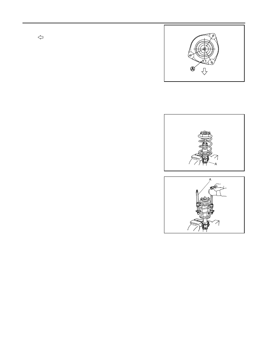
• Become it in ID letter (A) an illustration to the body front side.

• Perform final tightening of bolts and nuts, under unladen conditions

with tires on level ground.

Disassembly and Assembly

INFOID:0000000009948823

DISASSEMBLY

CAUTION:

Never damage strut assembly piston rod when removing components from strut assembly.
1.

Install strut attachment (A) [SST: ST35652000 (

)] to strut

assembly and secure it in a vise.

CAUTION:

When installing the strut attachment to strut assembly,
wrap a shop cloth around strut to protect from damage.

2.

Using a spring compressor (A) (commercial service tool), com-
press coil spring between strut mounting bearing and lower seat
(strut assembly) until coil spring with a spring compressor is
free.

CAUTION:

Be sure a spring compressor is securely attached to coil
spring. Compress coil spring.

3.

Check coil spring with a spring compressor between strut
mounting bearing and lower seat (strut assembly) is free. And
then remove piston rod lock nut while securing the piston rod tip
so that piston rod does not turn.

4.

Remove strut mounting insulator and strut mounting bearing,
and bound bumper from strut.

5.

After removing coil spring with a spring compressor (commercial service tool), then gradually release a
spring compressor.

CAUTION:

Loosen while making sure coil spring attachment position does not move.

6.

Remove the strut attachment [SST: ST35652000 (

)] from strut.

ASSEMBLY

1.

Install strut attachment [SST: ST35652000 (

)] to strut and secure it in a vise.

CAUTION:

When installing the strut attachment to strut assembly, wrap a shop cloth around strut to protect
from damage.

2.

Install bound bumper onto strut mounting insulator.

3.

Compress coil spring using a spring compressor (commercial service tool), and install it onto strut assem-
bly.

CAUTION:

: Vehicle front

JPEIA0023JP

JPEIA0006ZZ

JPEIA0168ZZ

FRONT COIL SPRING AND STRUT

FSU-11

< REMOVAL AND INSTALLATION >

C

D

F

G

H

I

J

K

L

M

A

B

FSU

N

O

P

• Face tube side of coil spring (1) downward. Align the

lower end (A) to lower seat (strut assembly) (2).

• Be sure a compressor is securely attached to coil spring.

Compress coil spring.

4.

Install strut mounting bearing and strut mounting insulator with bound bumper to strut.
• Installation position of strut mounting insulator is shown in the

figure.

5.

Secure piston rod tip so that piston rod does not turn, then
tighten piston rod lock nut with specified torque.

CAUTION:

Never reuse piston rod lock nut.

6.

Gradually release a spring compressor (commercial service
tool), and remove coil spring.

CAUTION:

Loosen while making sure coil spring attachment position does not move.

7.

Remove the strut attachment [SST: ST35652000 (

)] from strut assembly.

Inspection

INFOID:0000000009948824

INSPECTION AFTER DISASSEMBLY

Strut

Check the following items, and replace the parts if necessary.
• Strut for deformation, cracks or damage.
• Piston rod for damage, uneven wear or distortion.
• Oil leakage.

Strut Mounting Insulator and bound bumper Inspection

Check strut mounting insulator and bound bumper for cracks, wear or damage. Replace it if necessary.

Coil Spring

Check coil spring for cracks, wear or damage. Replace it if necessary.

INSPECTION AFTER INSTALLATION

1.

Check wheel sensor harness for proper connector. Refer to 

BRC-110, "FRONT WHEEL SENSOR :

Exploded View"

.

2.

Check wheel alignment. Refer to 

FSU-7, "Inspection"

.

3.

Adjust neutral position of steering angle sensor. Refer to 

BRC-9, "Special Repair Requirement"

.

Disposal

INFOID:0000000009948825

1.

Set strut assembly horizontally to the ground with the piston rod fully extracted.

JPEIA0095ZZ

: Vehicle front

JPEIA0023JP

FSU-12

< REMOVAL AND INSTALLATION >

FRONT COIL SPRING AND STRUT

2.

Drill 2 – 3 mm (0.08 – 0.12 in) hole at the position (

) from top

as shown in the figure to release gas gradually.

CAUTION:

• Wear eye protection (safety glasses).
• Wear gloves.
• Be careful with metal chips or oil blown out by the com-

pressed gas.

NOTE:
• Drill vertically in this direction (

).

• Directly to the outer tube avoiding brackets.
• The gas is clear, colorless, odorless, and harmless.

3.

Position the drilled hole downward and drain oil by moving the piston rod several times.

CAUTION:

Dispose of drained oil according to the law and local regulations.

A

: 20 – 30 mm (0.79 – 1.18 in)

JPEIA0160ZZ

TRANSVERSE LINK

FSU-13

< REMOVAL AND INSTALLATION >

C

D

F

G

H

I

J

K

L

M

A

B

FSU

N

O

P

TRANSVERSE LINK

Exploded View

INFOID:0000000009948826

Removal and Installation

INFOID:0000000009948827

REMOVAL

1.

Remove tires with power tool. Refer to 

WT-46, "Exploded View"

.

2.

Remove under cover. Refer to 

EXT-22, "Exploded View"

.

3.

Remove transverse link from steering knuckle. Refer to 

FAX-9, "Exploded View"

.

4.

Remove transverse link from suspension member.
NOTE:
Support the point around from upper link (right side) with a jack when removing transverse link (right side). 

INSTALLATION

Note the following, and install in the reverse order of removal.
• Perform final tightening of bolts and nuts at the front suspension member, under unladen conditions with

tires on level ground.

Inspection

INFOID:0000000009948828

INSPECTION AFTER REMOVAL

Transverse Link

Check the following items, and replace the part it necessary.
• Transverse link and bushing for deformation, cracks or damage.
• Ball joint boot for cracks or other damage, and also for grease leakage.

Swing Torque

1.

Manually move ball stud to confirm it moves smoothly with no binding.

2.

Move ball stud at least ten times by hand to check for smooth movement.

1.

Upper link (right side)

2.

Front suspension member

3.

Transverse link

Refer to 

GI-4, "Components"

 for symbols in the figure.

JPEIA0179GB


Content   ..  502  503  504  505   ..