Nissan Cube. Manual - part 410


  Index      Nissan     Nissan Cube (2014 year) - Service and Repair Manual


Search            


Content   ..  408  409  410  411   ..


Nissan Cube. Manual - part 410


EM-44

< REMOVAL AND INSTALLATION >

TIMING CHAIN

a.

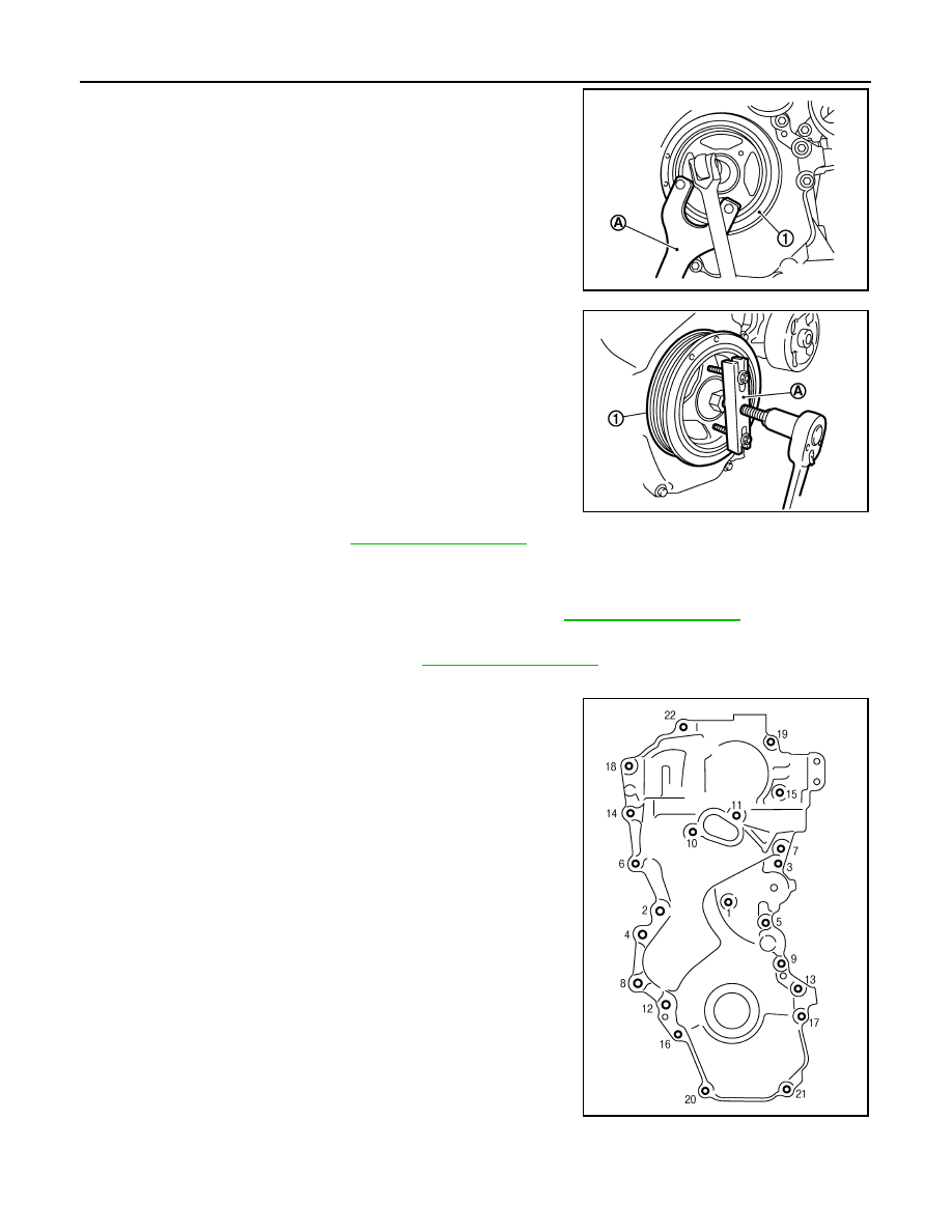
Fix crankshaft pulley (1) with a pulley holder (commercial ser-
vice tool) (A), loosen crankshaft pulley bolt, and locate bolt seat-
ing surface at 10 mm (0.39 in) from its original position.

CAUTION:

Never remove the crankshaft pulley bolt as they will be
used as a supporting point for the pulley puller [SST:
KV11103000 (

)].

b.

Attach a pulley puller [SST: KV11103000 (

)] (A) in the M6

thread hole on crankshaft pulley (1), and remove crankshaft pul-
ley. 

6.

Remove oil pan (lower). Refer to 

EM-32, "Exploded View"

.

NOTE:
If crankshaft sprocket and oil pump drive component are not removed, this step is unnecessary.

7.

Support the bottom surface of engine using a transmission jack, and then remove the engine mounting
bracket (RH) and the engine mounting insulator (RH). Refer to 

EM-74, "Exploded View"

.

8.

Remove intake valve timing control solenoid valve.

9.

Remove drive belt auto-tensioner. Refer to 

EM-23, "Exploded View"

.

10. Remove front cover with the following procedure:

a.

Loosen mounting bolts in the order of 22 to 1 as shown in the
figure.

PBIC3961E

PBIC3962E

PBIC3164J

TIMING CHAIN

EM-45

< REMOVAL AND INSTALLATION >

C

D

E

F

G

H

I

J

K

L

M

A

EM

N

P

O

b.

Cut liquid gasket by prying the position (

) shown in the figure,

and then remove the front cover.

CAUTION:

• Be careful not to damage the mating surface.
• A more adhesive liquid gasket is applied compared to pre-

vious types when shipped, so it should not be forced off
the position not specified.

11. Remove front oil seal from front cover. 

CAUTION:

Be careful not to damage front cover.
• Lift up front oil seal using a screwdriver.

12. Remove timing chain tensioner with the following procedure:

a.

Push in timing chain tensioner plunger. 

b.

Insert a stopper pin (A) into the body hole, and then fix it with the
plunger pushed in.
NOTE:
Use approximately 1.5 mm (0.059 in) diameter. hard metal pin
as a stopper pin.

c.

Remove timing chain tensioner (1).

13. Remove slack guide (2), tension guide (3) and timing chain (1).

CAUTION:

Never rotate each crankshaft and camshaft individually
while timing chain is removed. It causes interference
between valve and piston.
NOTE:
If timing chain is difficult to remove, remove camshaft sprocket
(EXH) first to remove timing chain.

14. Remove crankshaft sprocket and oil pump drive component with the following procedure:

PBIC3357J

PBIC3165J

JPBIA0830ZZ

EM-46

< REMOVAL AND INSTALLATION >

TIMING CHAIN

a.

Press stopper tab (A) in the direction shown in the figure to push
the oil pump chain tensioner slack guide (B) toward oil pump
chain tensioner (1).
• The oil pump chain tensioner slack guide is released by press-

ing the stopper tab. As the result, the oil pump chain tensioner
slack guide can be moved.

b.

Insert a stopper pin (D) into tensioner body hole (C) to secure
the oil pump chain tensioner slack guide.
NOTE:
Use a hard metal pin with the diameter of approximately 1.2 mm
(0.047 in) as a stopper pin.

c.

Remove oil pump chain tensioner.
• When the holes on lever and tensioner body cannot be

aligned, align these holes by slightly moving the oil pump
chain tensioner slack guide.

d.

Hold the WAF part of oil pump shaft [WAF: 10 mm (0.39 in)] (A),
and then loosen the oil pump sprocket bolt and remove it.

CAUTION:

• Secure the oil pump shaft with the WAF part.
• Never loosen the oil pump sprocket bolt by tightening the

oil pump drive chain.

e.

Remove crankshaft sprocket, oil pump sprocket, and oil pump
drive chain as a set.

15. Remove tension guide (front cover side) from front cover, if necessary.

INSTALLATION

CAUTION:

Do not reuse O-rings.
NOTE:

PBIC5314E

1

: Oil pan (upper)

2

: Oil pump

: Engine front

PBIC3539J

TIMING CHAIN

EM-47

< REMOVAL AND INSTALLATION >

C

D

E

F

G

H

I

J

K

L

M

A

EM

N

P

O

The figure shows the relationship between the matching mark on
each timing chain and that on the corresponding sprocket, with the
components installed.

*: There are two outer grooves in camshaft sprocket (INT). The wider one is a match-
ing mark.

1.

Check that crankshaft key points straight up.

2.

If the tension guide (front cover side) is removed, install it to the front cover.

CAUTION:

Check the joint condition by sound or feeling.

3.

Install crankshaft sprocket (2), oil pump sprocket (3), and oil
pump drive chain (1).

• Install it by aligning matching marks on each sprockets and oil

pump drive chain. 

• If these matching marks are not aligned, rotate the oil pump

shaft slightly to correct the position.

CAUTION:

Check matching mark position of each sprockets after
installing the oil pump drive chain.

1

: Timing chain 

2

: Camshaft sprocket (EXH)

3

:  Slack  guide

4

: Timing chain tensioner

5

: Oil pump sprocket

6

: Oil pump drive chain

7

: Oil pump chain tensioner

8

: Crankshaft sprocket

9

: Tension guide

10

: Camshaft sprocket (INT)

A

: Matching mark (dark blue link)

B

: Matching mark (stamping)

C

: Crankshaft key position (straight up)

D

: Matching mark (stamping)

E

: Matching mark (orange link)

F

: Matching mark (outer groove*)

A

: Matching mark (stamping)

B

: Matching mark (orange link)

C

: Matching mark (dark blue link)

JPBIA0831ZZ

PBIC3171J


Content   ..  408  409  410  411   ..