Nissan Cube. Manual - part 378


  Index      Nissan     Nissan Cube (2014 year) - Service and Repair Manual


Search            


Content   ..  376  377  378  379   ..


Nissan Cube. Manual - part 378


EC-398

< DTC/CIRCUIT DIAGNOSIS >

[MR18DE]

ASCD BRAKE SWITCH

• 10 A fuse (No. 2)
• Harness for open or short between ASCD brake switch and fuse

>> Repair open circuit or short to ground or short to power in harness or connectors.

3.

CHECK ASCD CLUTCH SWITCH POWER SUPPLY CIRCUIT

1.

Turn ignition switch OFF.

2.

Disconnect ASCD clutch switch harness connector.

3.

Turn ignition switch ON.

4.

Check the voltage between ASCD clutch switch harness connector and ground.

Is the inspection result normal?

YES

>> GO TO 5.

NO

>> GO TO 4.

4.

DETECT MALFUNCTIONING PART

Check the following.
• Harness connectors E105, M77
• 10 A fuse (No. 2)
• Harness for open or short between ASCD clutch switch and fuse

>> Repair open circuit or short to ground or short to power in harness or connectors.

5.

CHECK ASCD BRAKE SWITCH POWER SUPPLY CIRCUIT-II

1.

Turn ignition switch OFF.

2.

Disconnect ASCD brake switch harness connector.

3.

Check the continuity between ASCD clutch switch harness connector and ASCD brake switch harness
connector.

4.

Also check harness for short to ground and short to power.

Is the inspection result normal?

YES

>> GO TO 6.

NO

>> Repair open circuit or short to ground or short to power in harness or connectors.

6.

CHECK ASCD CLUTCH SWITCH

Refer to 

EC-399, "Component Inspection (ASCD Clutch Switch)"

.

Is the inspection result normal?

YES

>> GO TO 9.

NO

>> Replace ASCD clutch switch. Refer to 

CL-11, "Exploded View"

.

7.

CHECK ASCD BRAKE SWITCH INPUT SIGNAL CIRCUIT FOR OPEN AND SHORT

1.

Turn ignition switch OFF.

2.

Disconnect ECM harness connector.

3.

Check the continuity between ASCD brake switch harness connector and ECM harness connector.
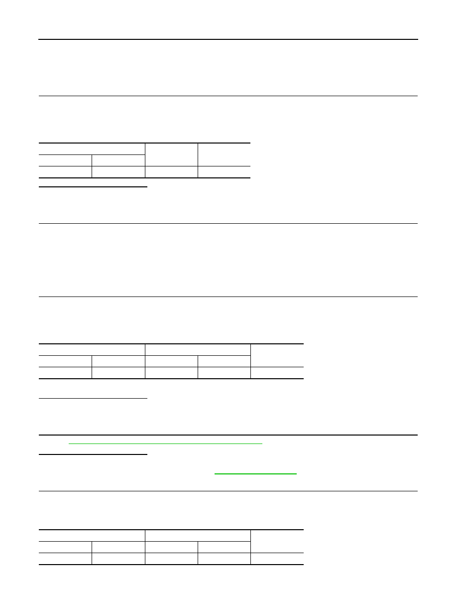
ASCD clutch switch

Ground

Voltage

Connector

Terminal

E111

3

Ground

Battery voltage

ASCD clutch switch

ASCD brake switch

Continuity

Connector

Terminal

Connector

Terminal

E111

4

E112

1

Existed

ASCD brake switch

ECM

Continuity

Connector

Terminal

Connector

Terminal

E112

2

E16

100

Existed

ASCD BRAKE SWITCH

EC-399

< DTC/CIRCUIT DIAGNOSIS >

[MR18DE]

C

D

E

F

G

H

I

J

K

L

M

A

EC

N

P

O

4.

Also check harness for short to ground and short to power.

Is the inspection result normal?

YES

>> GO TO 8.

NO

>> Repair open circuit or short to ground or short to power in harness or connectors.

8.

CHECK ASCD BRAKE SWITCH

Refer to 

EC-399, "Component Inspection (ASCD Brake Switch)"

.

Is the inspection result normal?

YES

>> GO TO 9.

NO

>> Replace ASCD brake switch. Refer to 

BR-17, "Exploded View"

.

9.

CHECK INTERMITTENT INCIDENT

Refer to 

GI-40, "Intermittent Incident"

.

>> INSPECTION END

Component Inspection (ASCD Brake Switch)

INFOID:0000000009947539

1.

CHECK ASCD BRAKE SWITCH-I

1.

Turn ignition switch OFF.

2.

Disconnect ASCD brake switch harness connector.

3.

Check the continuity between ASCD brake switch terminals under the following conditions.

Is the inspection result normal?

YES

>> INSPECTION END

NO

>> GO TO 2.

2.

CHECK ASCD BRAKE SWITCH-II

1.

Adjust ASCD brake switch installation. Refer to 

BR-7, "Inspection and Adjustment"

.

2.

Check the continuity between ASCD brake switch terminals under the following conditions.

Is the inspection result normal?

YES

>> INSPECTION END

NO

>> Replace ASCD brake switch. Refer to 

BR-17, "Exploded View"

.

Component Inspection (ASCD Clutch Switch)

INFOID:0000000009947540

1.

CHECK ASCD CLUTCH SWITCH-I

1.

Turn ignition switch OFF.

2.

Disconnect ASCD clutch switch harness connector.

3.

Check the continuity between ASCD clutch switch terminals under the following conditions.

Terminals

Condition

Continuity

1 and 2

Brake pedal

Fully released

Existed

Slightly de-
pressed

Not existed

Terminals

Condition

Continuity

1 and 2

Brake pedal

Fully released

Existed

Slightly de-
pressed

Not existed

Terminals

Condition

Continuity

1 and 2

Clutch pedal

Fully released

Existed

Slightly de-
pressed

Not existed

EC-400

< DTC/CIRCUIT DIAGNOSIS >

[MR18DE]

ASCD BRAKE SWITCH

Is the inspection result normal?

YES

>> INSPECTION END

NO

>> GO TO 2.

2.

CHECK ASCD CLUTCH SWITCH-II

1.

Adjust ASCD clutch switch installation. Refer to 

BR-7, "Inspection and Adjustment"

.

2.

Check the continuity between ASCD clutch switch terminals under the following conditions.

Is the inspection result normal?

YES

>> INSPECTION END

NO

>> Replace ASCD clutch switch. Refer to 

CL-11, "Exploded View"

.

Terminals

Condition

Continuity

1 and 2

Clutch pedal

Fully released

Existed

Slightly de-
pressed

Not existed

ASCD INDICATOR

EC-401

< DTC/CIRCUIT DIAGNOSIS >

[MR18DE]

C

D

E

F

G

H

I

J

K

L

M

A

EC

N

P

O

ASCD INDICATOR

Description

INFOID:0000000009947541

ASCD indicator lamp illuminates to indicate ASCD operation status. Lamp has two indicators, CRUISE and
SET, and is integrated in combination meter.
CRUISE lamp illuminates when MAIN switch on ASCD steering switch is turned ON to indicated that ASCD
system is ready for operation.
SET lamp illuminates when following conditions are met. 
• CRUISE lamp is illuminated.
• SET/COAST switch on ASCD steering switch is turned ON while vehicle speed is within the range of ASCD

setting.

SET lamp remains lit during ASCD control.
Refer to 

EC-65, "System Description"

 for the ASCD function.

Component Function Check

INFOID:0000000009947542

1.

ASCD INDICATOR FUNCTION

Check ASCD indicator under the following conditions.

Is the inspection result normal?

YES

>> INSPECTION END

NO

>> Go to 

EC-401, "Diagnosis Procedure"

.

Diagnosis Procedure

INFOID:0000000009947543

1.

CHECK DTC

Check that DTC U1001 is not displayed.
Is DTC detected?

NO

>> GO TO 2.

YES

>> Perform trouble diagnosis for DTC U1001. Refer to 

EC-133, "DTC Logic"

.

2.

CHECK COMBINATION METER OPERATION

Refer to 

MWI-6, "METER SYSTEM : System Description"

.

Is the inspection result normal?

YES

>> GO TO 3.

NO

>> Check combination meter circuit. Refer to  

MWI-6, "METER SYSTEM : System Diagram"

.

3.

CHECK INTERMITTENT INCIDENT

Refer to 

GI-40, "Intermittent Incident"

.

>> INSPECTION END

ASCD indicator

Condition

Specification

CRUISE LAMP

• Ignition switch: ON

• MAIN switch: Pressed at the 

1st time 

at the 2nd time

ON 

 OFF

SET LAMP

• MAIN switch: ON
• When vehicle speed: Be-

tween 40 km/h (25 MPH) and 
160 km/h (100 MPH)

• ASCD: Operating

ON

• ASCD: Not operating

OFF


Content   ..  376  377  378  379   ..