Nissan Cube. Manual - part 348
EC-278
< DTC/CIRCUIT DIAGNOSIS >
[MR18DE]
P0451 EVAP CONTROL SYSTEM PRESSURE SENSOR
Is the inspection result normal?
YES
>> GO TO 3.
NO
>> Repair or replace harness connector.
3.
CHECK EVAP CONTROL SYSTEM PRESSURE SENSOR POWER SUPPLY CIRCUIT
1.
Turn ignition switch ON.
2.
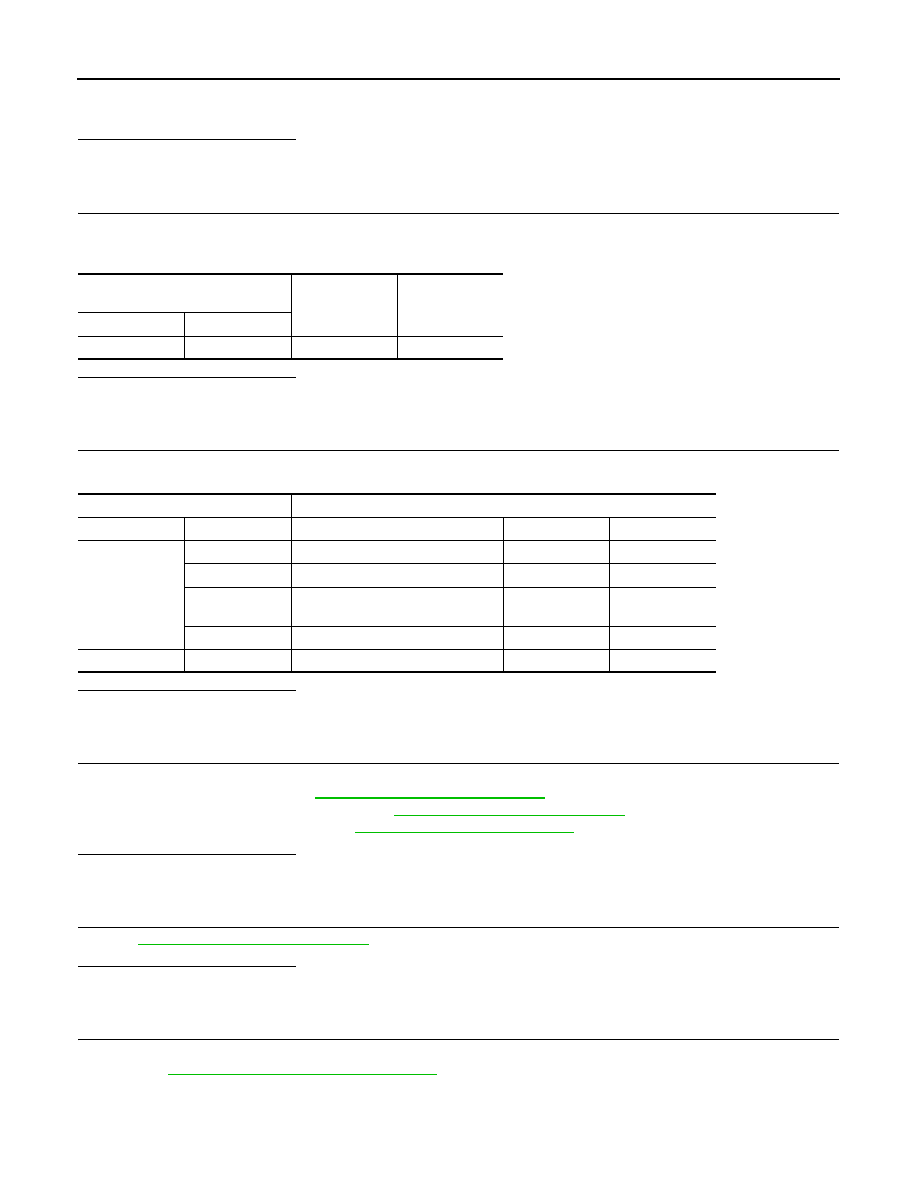
Check the voltage between EVAP control system pressure sensor harness connector and ground.
Is the inspection result normal?
YES
>> GO TO 8.
NO
>> GO TO 4.
4.
CHECK SENSOR POWER SUPPLY CIRCUITS
Check harness for short to power and short to ground, between the following terminals.
Is the inspection result normal?
YES
>> GO TO 5.
NO
>> Repair short to ground or short to power in harness or connectors.
5.
CHECK COMPONENTS
Check the following.
• Battery current sensor (Refer to
EC-337, "Component Inspection"
.)
• Crankshaft position sensor (POS) (Refer to
EC-244, "Component Inspection"
• Refrigerant pressure sensor (Refer to
.)
Is the inspection result normal?
YES
>> GO TO 6.
NO
>> Replace malfunctioning component.
6.
CHECK APP SENSOR
EC-385, "Component Inspection"
Is the inspection result normal?
YES
>> GO TO 9.
NO
>> GO TO 7.
7.
REPLACE ACCELERATOR PEDAL ASSEMBLY
1.
Replace accelerator pedal assembly
2.
EC-385, "Special Repair Requirement"
>> INSPECTION END
Water should not exist.
EVAP control system pressure sen-
sor
Ground
Voltage
Connector
Terminal
B21
3
Ground
Approx. 5 V
ECM
Sensor
Connector
Terminal
Name
Connector
Terminal
F8
74
Refrigerant pressure sensor
E49
3
75
CKP sensor (POS)
F20
1
76
EVAP control system pressure sen-
sor
B21
3
77
Battery current sensor
F53
1
E16
102
APP sensor
E110
5