Nissan Cube. Manual - part 204


  Index      Nissan     Nissan Cube (2014 year) - Service and Repair Manual


Search            


Content   ..  202  203  204  205   ..


Nissan Cube. Manual - part 204


DLK-82

< DTC/CIRCUIT DIAGNOSIS >

[WITH INTELLIGENT KEY SYSTEM]

UNLOCK SENSOR

Is the inspection result normal?

YES

>> Replace BCM. Refer to 

BCS-88, "Removal and Installation"

.

NO

>> Repair or replace harness.

3.

CHECK UNLOCK SENSOR GROUND CIRCUIT

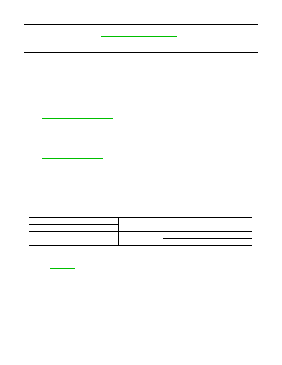
Check continuity between front door lock assembly (driver side) harness connector and ground.

Is the inspection result normal?

YES

>> GO TO 4.

NO

>> Repair or replace harness.

4.

CHECK UNLOCK SENSOR 

Refer to 

DLK-82, "Component Inspection"

Is the inspection result normal?

YES

>> GO TO 5.

NO

>> Replace front door lock assembly (driver side). Refer to 

DLK-212, "DOOR LOCK : Removal and

Installation"

.

5.

CHECK INTERMITTENT INCIDENT 

Refer to 

GI-40, "Intermittent Incident"

.

>> INSPECTION END

Component Inspection

INFOID:0000000009950528

1.

CHECK UNLOCK SENSOR

1.

Turn ignition switch OFF.

2.

Disconnect front door lock assembly (driver side) connector.

3.

Check continuity between front door lock assembly (driver side) terminals.

Is the inspection result normal?

YES

>> INSPECTION END

NO

>> Replace front door lock assembly (driver side). Refer to 

DLK-212, "DOOR LOCK : Removal and

Installation"

.

Front door lock assembly (driver side)

Ground

Continuity 

Connector

Terminal

D9

4

Existed

Front door lock assembly (driver side)

Condition

Continuity

Terminal

3

4

Driver side door

Unlock

Existed

Lock

Not existed

INTELLIGENT KEY WARNING BUZZER

DLK-83

< DTC/CIRCUIT DIAGNOSIS >

[WITH INTELLIGENT KEY SYSTEM]

C

D

E

F

G

H

I

J

L

M

A

B

DLK

N

O

P

INTELLIGENT KEY WARNING BUZZER

Description

INFOID:0000000009950529

Answers back and warns for an inappropriate operation.

Component Function Check

INFOID:0000000009950530

1.

CHECK FUNCTION

1.

Use CONSULT to perform BCM Active Test (“OUTSIDE BUZZER”).

2.

Touch “ON” to check that it works normally.

Is the inspection result normal?

YES

>> Intelligent Key warning buzzer is OK.

NO

>> Refer to 

DLK-83, "Diagnosis Procedure"

.

Diagnosis Procedure

INFOID:0000000009950531

1.

CHECK FUSE

1.

Turn ignition switch OFF.

2.

Check 10 A fuse, [No. 10, located in fuse block (J/B)].

Is the inspection result normal?

YES

>> GO TO 2.

NO

>> Replace the blown fuse after repairing the affected circuit if a fuse is blown.

2.

CHECK INTELLIGENT KEY WARNING BUZZER POWER SUPPLY CIRCUIT

1.

Disconnect Intelligent Key warning buzzer connector.

2.

Check voltage between Intelligent Key warning buzzer harness connector and ground.

Is the inspection result normal?

YES

>> GO TO 3.

NO

>> Repair or replace harness.

3.

CHECK INTELLIGENT KEY WARNING BUZZER CIRCUIT

1.

Disconnect BCM connector.

2.

Check continuity between BCM harness connector and Intelligent Key warning buzzer harness connector.

3.

Check continuity between BCM harness connector and ground.

Is the inspection result normal?

YES

>> GO TO 4.

NO

>> Repair or replace harness.

4.

CHECK INTELLIGENT KEY WARNING BUZZER

Refer to 

DLK-84, "Component Inspection"

.

(+)

(–)

Voltage (V)

(Approx.)

Intelligent Key warning buzzer

Connector

Terminal

E25

1

Ground

Battery voltage

BCM

Intelligent Key warning buzzer

Continuity 

Connector

Terminal

Connector

Terminal

M71

93

E25

3

Existed

BCM

Ground

Continuity 

Connector

Terminal

M71

93

Not existed

DLK-84

< DTC/CIRCUIT DIAGNOSIS >

[WITH INTELLIGENT KEY SYSTEM]

INTELLIGENT KEY WARNING BUZZER

Is the inspection result normal?

YES

>> Replace BCM. Refer to 

BCS-88, "Removal and Installation"

.

NO

>> Replace Intelligent Key warning buzzer. Refer to 

DLK-228, "Removal and Installation"

.

Component Inspection

INFOID:0000000009950532

1.

CHECK INTELLIGENT KEY WARNING BUZZER

1.

Turn ignition switch OFF.

2.

Disconnect Intelligent Key warning buzzer connector.

3.

Connect battery power supply directly to Intelligent Key warning buzzer terminals and check the opera-
tion.

Is the inspection result normal?

YES

>> INSPECTION END

NO

>> Replace Intelligent Key warning buzzer. Refer to 

DLK-228, "Removal and Installation"

.

Intelligent Key warning buzzer

Operation

Terminal

(+)

(

)

1

3

Buzzer sounds

INTELLIGENT KEY

DLK-85

< DTC/CIRCUIT DIAGNOSIS >

[WITH INTELLIGENT KEY SYSTEM]

C

D

E

F

G

H

I

J

L

M

A

B

DLK

N

O

P

INTELLIGENT KEY

Description

INFOID:0000000009950533

The following functions are available when having and carrying electronic ID.
• Door lock/unlock
• Engine start
Remote control entry function and panic alarm function are available when operating on button.

Component Function Check

INFOID:0000000009950534

1.

CHECK FUNCTION

Check (“RKE OPE COUN1”) in Data Monitor mode using CONSULT.

Is the inspection result normal?

YES

>> Intelligent Key is OK.

NO

>> Refer to 

DLK-85, "Diagnosis Procedure"

.

Diagnosis Procedure

INFOID:0000000009950535

1.

CHECK INTELLIGENT KEY BATTERY

Check by connecting a resistance (approximately 300

) so that the

current value becomes about 10 mA. Refer to 

DLK-230, "Removal

and Installation"

.

Is the measurement value within the specification?

YES

>> Replace Intelligent Key. 

NO

>> Replace Intelligent Key battery. Refer to 

DLK-230,

"Removal and Installation"

.

Monitor item

Condition

RKE OPE COUN1

Check that the numerical value is changing while operating on the Intelligent Key.

Standard

: Approx. 2.5 - 3.0V

OCC0607D


Content   ..  202  203  204  205   ..