Nissan Cube. Manual - part 105
BRC-70
< DTC/CIRCUIT DIAGNOSIS >
[VDC/TCS/ABS]
C1164, C1165 CV SYSTEM
C1164, C1165 CV SYSTEM
Description
INFOID:0000000009949984
The cut valve shuts off the normal brake fluid path from the master cylinder, when VDC/TCS is activated.
DTC Logic
INFOID:0000000009949985
DTC DETECTION LOGIC
DTC CONFIRMATION PROCEDURE
1.
PRECONDITIONING
If “DTC CONFIRMATION PROCEDURE” has been previously conducted, always turn ignition switch OFF and
wait at least 10 seconds before conducting the next test.
>> GO TO 2.
2.
DTC REPRODUCTION PROCEDURE
1.
Turn the ignition switch ON.
2.
Perform self-diagnosis for “ABS” with CONSULT.
Is DTC “C1164” or “C1165” detected?
YES
>> Proceed to diagnosis procedure. Refer to
.
NO
>> INSPECTION END
Diagnosis Procedure
INFOID:0000000009949986
1.
CHECK ACTUATOR RELAY POWER SUPPLY CIRCUIT
1.
Turn the ignition switch ON.
2.
Disconnect ABS actuator and electric unit (control unit) harness connector.
3.
Check the 30A fusible link (K).
4.
Check the voltage between ABS actuator and electric unit (control unit) harness connector and ground.
Is the inspection result normal?
YES
>> GO TO 2.
NO
>> Repair or replace damaged parts.
2.
CHECK SOLENOID, VDC SWITCH-OVER VALVE AND ACTUATOR RELAY GROUND CIRCUIT
Check the continuity between ABS actuator and electric unit (control unit) harness connector and ground.
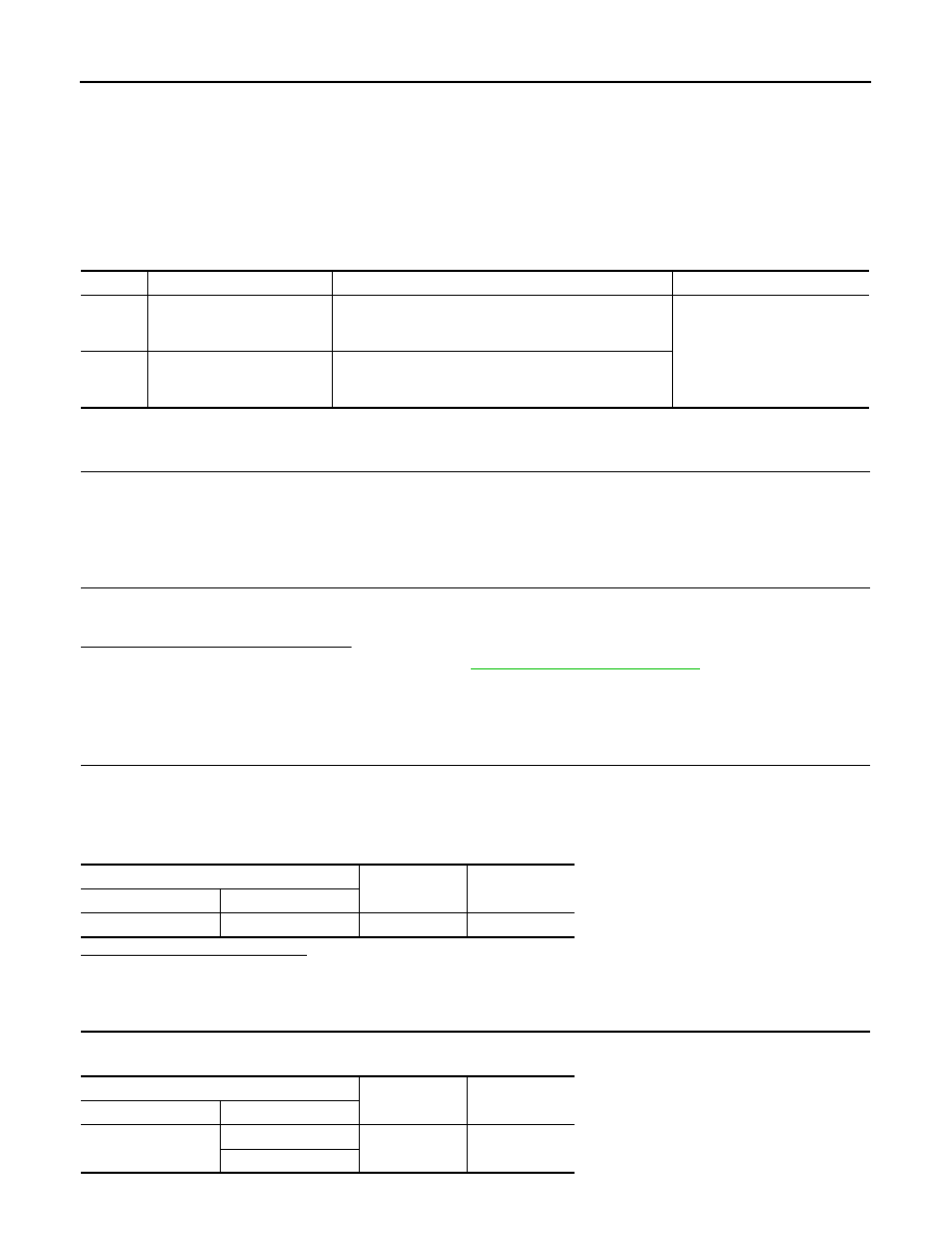
DTC
Display item
Malfunction detected condition
Possible cause
C1164
CV 1
VDC switch-over solenoid valve (CV1) on the primary
side is open circuit or shorted, or the control line is open
or shorted to the power supply or the ground.
• Harness or connector
• ABS actuator and electric unit
(control unit)
C1165
CV 2
VDC switch-over solenoid valve (CV2) on the secondary
side is open circuit or shorted, or the control line is open
or shorted to the power supply or the ground.
ABS actuator and electric unit (control unit)
—
Voltage
Connector
Terminal
E36
3
Ground
Battery voltage
ABS actuator and electric unit (control unit)
—
Continuity
Connector
Terminal
E36
1
Ground
Existed
4