Nissan Versa Sedan. Manual - part 797
TM-94
< SYSTEM DESCRIPTION >
[4AT: RE4F03C]
DIAGNOSIS SYSTEM (TCM)
WORK SUPPORT
SELF DIAGNOSTIC RESULTS
.
DTC at 1st trip and method to read DTC
• DTC (P0705, P0711, P0720, etc.) is specified by SAE J2012/ISO 15031-6.
• DTC and DTC at 1st trip are displayed on “Self Diagnostic results” of CONSULT. “ Timing” shows current
malfunction or malfunction in the past.
If current DTC is detected, “timing” is “present”. If the “timing” is “memorized”, it is the malfunction occurred
in the past. According to “ignition counter” in “FFD”, the number (trip) of operation without malfunction of the
DTC can be checked.
• When the DTC at the 1st trip is detected, the “timing” is displayed as “1t”.
DTC deletion method
NOTE:
If the ignition switch is left ON after repair, turn OFF the ignition switch and wait for 10 seconds or more. Then,
turn ignition ON again. (Engine stop)
1. Touch “TRANSMISSION” of CONSULT.
2. Touch “Self Diagnostic Result”.
3. Touch “Erase”. (DTC memorized in TCM is erased.)
IGN counter
The ignition counter is displayed in “FFD” and the number of times of satisfied “Driving Pattern A” is displayed
after normal recovery of DTC. Refer to
TM-91, "DIAGNOSIS DESCRIPTION : Counter System"
• If malfunction (DTC) is currently detected, “0” is displayed.
• After normal recovery, every time “Driving Pattern A” is satisfied, the display value increases from 1
→ 2 →
3...38
→ 39.
• When MIL turns OFF due to the malfunction and the counter reaches 40, the DTC is erased.
NOTE:
The counter display of “40” cannot be checked.
DATA MONITOR
NOTE:
The following table includes information (items) inapplicable to this vehicle. For information (items) applicable
to this vehicle, refer to CONSULT display items.
X: Standard, —: Not applicable, : Option
CAN Diagnostic Support
Monitor
It monitors the starts of CAN communication.
DTC Work Support
DTC reproduction procedure can be performed speedily and precisely.
ECU Identification
Display the ECU identification number (part number etc.) of the selected system.
CALIB DATA
The calibration data status of TCM can be checked.
Diagnostic test mode
Function
Item name
Description
ERASE CALIBRATION DATA
Erases the “CALIBRATION DATA” stored by the TCM.
ERASE LEARNING VALUE
Erases the “LEARNING VALUE” stored by the TCM.
ERASE MEMORY DATA
Erases both the “CALIBRATION DATA” and “LEARNING VALUE”.
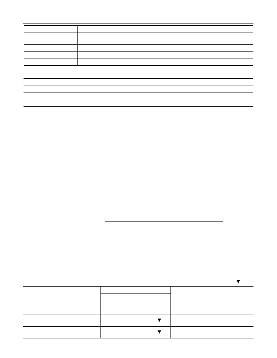
Monitored item (Unit)
Monitor Item Selection
Remarks
ECU IN-
PUT SIG-
NALS
MAIN SIG-
NALS
SELEC-
TION
FROM
ITEM
VHCL/S SE-A/T
(km/h or mph)
X
X
Displays the vehicle speed calculated by the
TCM from the output shaft revolution.
ESTM VSP SIG
(km/h or mph)
X
—
Displays the vehicle speed signal received via
CAN communication.