Nissan Versa Sedan. Manual - part 353
P2122, P2123 APP SENSOR
EC-411
< DTC/CIRCUIT DIAGNOSIS >
[HR16DE]
C
D
E
F
G
H
I
J
K
L
M
A
EC
N
P
O
Is the inspection result normal?
YES
>> INSPECTION END
NO
>> GO TO 2.
2.
REPLACE ACCELERATOR PEDAL ASSEMBLY
Replace accelerator pedal assembly. Refer to
>> INSPECTION END
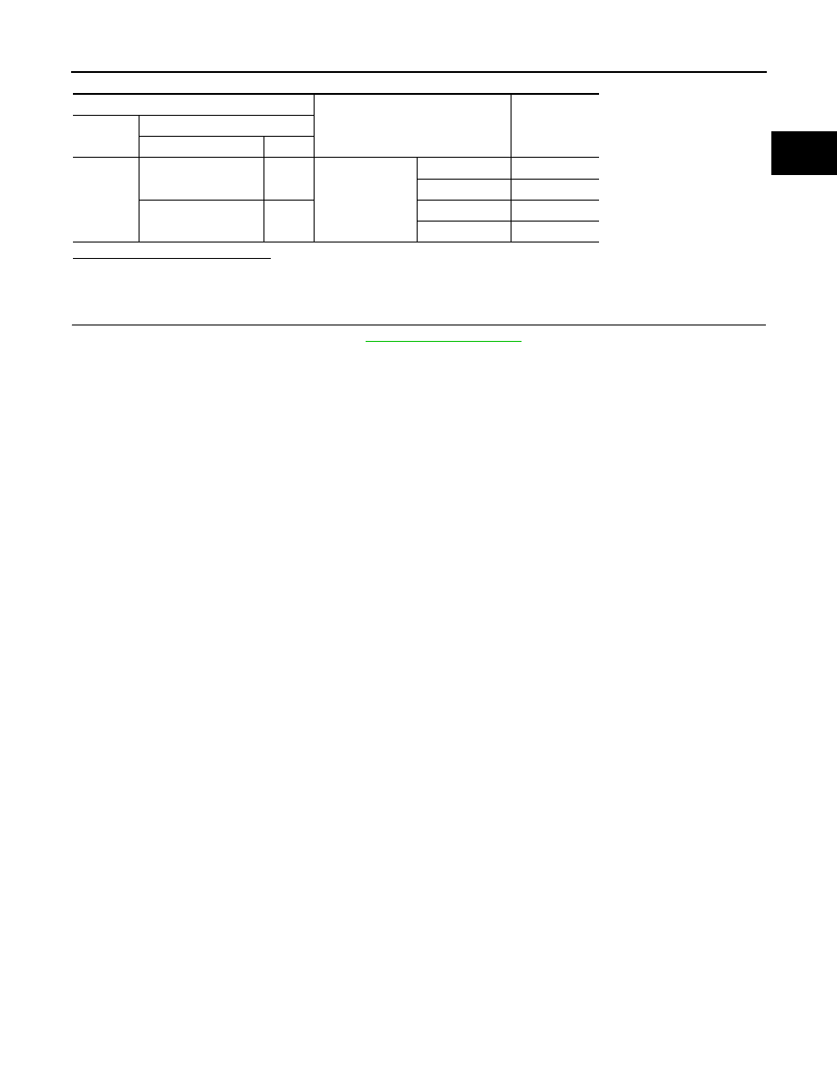
ECM
Condition
Voltage
Connector
Terminal
+
−
E16
110
(APP sensor 1 signal)
111
Accelerator pedal
Fully released
0.6 - 0.9 V
Fully depressed
3.9 - 4.7 V
103
(APP sensor 2 signal)
104
Fully released
0.3 - 0.6 V
Fully depressed
1.95 - 2.4 V