Nissan Versa Sedan. Manual - part 313
P0181 FTT SENSOR
EC-251
< DTC/CIRCUIT DIAGNOSIS >
[HR16DE]
C
D
E
F
G
H
I
J
K
L
M
A
EC
N
P
O
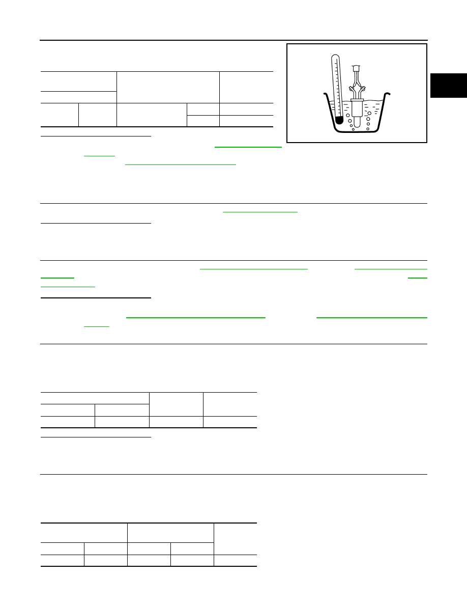
4. Check resistance between fuel level sensor unit and fuel pump
terminals by heating with hot water as shown in the figure.
Is the inspection result normal?
YES
>> Check intermittent incident. Refer to
NO
>> Proceed to
.
Diagnosis Procedure
INFOID:0000000009267136
1.
INSPECTION START
Confirm the detected malfunction (A or B). Refer to
.
Which malfunction is detected?
A
>> GO TO 2.
B
>> GO TO 6.
2.
CHECK DTC WITH COMBINATION METER
Check DTC with combination meter. Refer to
(TYPE A) or
(TYPE B). Check the vehicle type to confirm the service information in MWI section. Refer to
.
Is the inspection result normal?
YES
>> GO TO 3.
NO
>> Proceed to
MWI-46, "Component Function Check"
(TYPE A) or
(TYPE B).
3.
CHECK FUEL TANK TEMPERATURE (FTT) SENSOR POWER
1. Turn ignition switch OFF.
2. Disconnect fuel level sensor unit and fuel pump harness connector.
3. Turn ignition switch ON.
4. Check the voltage between fuel level sensor unit and fuel pump harness connector and ground.
Is the inspection result normal?
YES
>> GO TO 5.
NO
>> GO TO 4.
4.
CHECK FUEL TANK TEMPERATURE (FTT) SENSOR POWER SUPPLY CIRCUIT
1. Turn ignition switch OFF.
2. Disconnect ECM harness connector.
3. Check the continuity between fuel level sensor unit and fuel pump harness connector and ECM harness
connector.
4. Also check harness for short to ground and to power.
Fuel level sensor unit
and fuel pump
Condition
Resistance (k
Ω)
Terminal
4
5
Temperature [
°C (°F)]
20 (68)
2.3 – 2.7
50 (122)
0.79 – 0.90
JMBIA0167ZZ
Fuel level sensor unit and fuel pump
Ground
Voltage
(Approx.)
Connector
Terminal
B44
4
Ground
5 V
Fuel level sensor unit and
fuel pump
ECM
Continuity
Connector
Terminal
Connector
Terminal
B44
4
F11
42
Existed