Nissan Rogue. Manual - part 748


  Index      Nissan     Nissan Rogue (2015 year) - Service and Repair Manual


Search            


Content   ..  746  747  748  749   ..


Nissan Rogue. Manual - part 748


HAC-14

< SYSTEM DESCRIPTION >

[AUTOMATIC AIR CONDITIONING]

SYSTEM

• Rotation of motor is transmitted to air mix door (driver side) [upper air mix door (driver side) and lower air mix

door (driver side)] by link, rod and lever, then air flow temperature (driver side) is switched.
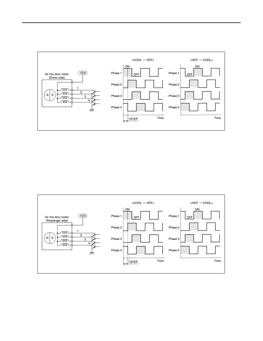
DRIVE METHOD

• The 4 drive coils are excited in sequence in order to drive the motor.

• Direction of rotation is changeable by recomposing pattern of excitation.

AIR MIX DOOR MOTOR (PASSENGER SIDE) 

DESCRIPTION

• The step motor system is adopted for air mix door motor (passenger side).

• When a drive signal is input from A/C auto amp. to door motor, a step motor built into the door motor rotates

according to the drive signal, and then stops at the target door position.

• Rotation of motor is transmitted to air mix door (passenger side) [upper air mix door (passenger side) and

lower air mix door (passenger side)] by link, rod and lever, then air flow temperature (passenger side) is

switched.

DRIVE METHOD

• The 4 drive coils are excited in sequence in order to drive the motor.

• Direction of rotation is changeable by recomposing pattern of excitation.

MODE DOOR MOTOR

DESCRIPTION

• The step motor system is adopted for mode door motor.

• When a drive signal is input from A/C auto amp. to door motor, a step motor built into the door motor rotates

according to the drive signal, and then stops at the target door position.

• Rotation of motor is transmitted to mode door (center ventilator and defroster door, sub defroster door, side

ventilator door, and foot door) by link, rod, and lever, then air outlet is switched.

DRIVE METHOD

• The 4 drive coils are excited in sequence in order to drive the motor.

JMIIA1954GB

JMIIA1955GB

SYSTEM

HAC-15

< SYSTEM DESCRIPTION >

[AUTOMATIC AIR CONDITIONING]

C

D

E

F

G

H

J

K

L

M

A

B

HAC

N

O

P

• Direction of rotation is changeable by recomposing pattern of excitation.

INTAKE DOOR MOTOR

DESCRIPTION

• The step motor system is adopted for intake door motor.

• When a drive signal is input from A/C auto amp. to door motor, a step motor built into the door motor rotates

according to the drive signal, and then stops at the target door position.

• Rotation of motor is transmitted to intake door, then air flow is switched.

DRIVE METHOD

• The 4 drive coils are excited in sequence in order to drive the motor.

• Direction of rotation is changeable by recomposing pattern of excitation.

SWITCHES AND THEIR CONTROL FUNCTION

JZIIA0033GB

JMIIA1954GB

HAC-16

< SYSTEM DESCRIPTION >

[AUTOMATIC AIR CONDITIONING]

SYSTEM

NOTE:

The sub defroster door and side ventilator door include a permanent opening and does not fully close.

Intake door

Blower motor

Air conditioner filter

Evaporator

Heater core

Air mix door (driver side/passenger 
side)

Foot door

Side ventilator door

Sub defroster door

Center ventilator and defroster door

Fresh air intake

Recirculation air

Discharge air

Defroster

Center ventilator

Side ventilator

Rear ventilator

Front foot

Rear foot

JMIIA3449ZZ

SYSTEM

HAC-17

< SYSTEM DESCRIPTION >

[AUTOMATIC AIR CONDITIONING]

C

D

E

F

G

H

J

K

L

M

A

B

HAC

N

O

P

*: Inlet status is displayed by indicator during activating automatic control

AIR DISTRIBUTION

Switch position

Door position

Mode door

In

ta

ke

 do

or

Air mix door

Ce

nt

er

 v

en

til

at

or

 a

nd

 de

fr

ost

er 

do

or

S

ub

 de

fros

te

r do

or

Si

de

 v

en

til

at

or

 do

or

Fo

ot doo

r

Driver side

Pa

ss

en

ge

r si

de

AUTO switch

AUTO

MODE switch

DEF switch

REC switch

*

FRE switch

*

Temperature control dial 
(Driver side)

DUAL 
switch: 
OFF

Full cold

18

°C

18.5

°C – 31.5°C

AUTO

Full hot

32

°C

Temperature control dial 
(Driver side)

DUAL 
switch: 
ON

Full cold

18

°C

18.5

°C – 31.5°C

AUTO

Full hot

32

°C

Temperature control dial 
(Passenger side)

Full cold

18

°C

18.5

°C – 31.5°C

AUTO

Full hot

32

°C

ON·OFF switch

OFF

Discharge air flow

MODE/DEF set-

ting position

Air outlet/distribution

Ventilator

Foot

Defroster

Front

Rear

Front

Rear

Center

Side

47%

38%

15%

25%

34%

13%

18%

10%


Content   ..  746  747  748  749   ..