Nissan Rogue. Manual - part 567


  Index      Nissan     Nissan Rogue (2015 year) - Service and Repair Manual


Search            


Content   ..  565  566  567  568   ..


Nissan Rogue. Manual - part 567


EXHAUST MANIFOLD AND THREE WAY CATALYST

EM-33

< REMOVAL AND INSTALLATION >

C

D

E

F

G

H

I

J

K

L

M

A

EM

N

P

O

8. Remove the air fuel ratio (A/F) sensor 1 using Tool, (if necessary).

CAUTION:

• Clean exhaust manifold and three way catalyst port securing air fuel ratio (A/F) sensor 1 with

anti-seize lubricant, or equivalent.

• Be careful not to damage air fuel ratio (A/F) sensor.

• Discard any air fuel ratio (A/F) sensor which has been dropped from a height of more than 0.5 m

(19.7 in) onto a hard surface such as a concrete floor; replace with a new one.

9. Detach front exhaust tube from exhaust manifold and three way catalyst. Discard the gasket. Refer to 

EX-

5, "Exploded View"

.

10. Remove the exhaust manifold cover (upper).
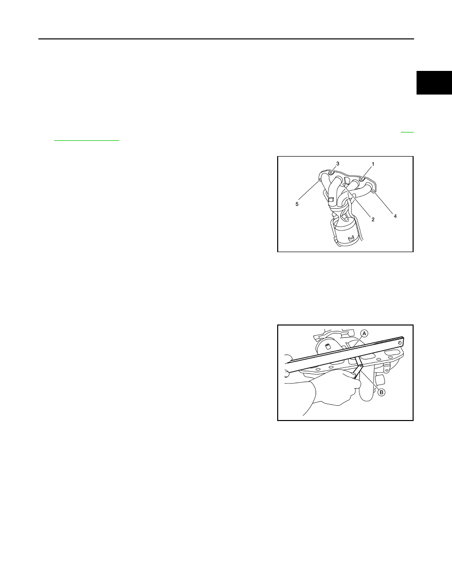
11. Loosen the exhaust manifold and three way catalyst nuts in the

reverse order as shown.

12. Remove exhaust manifold and three way catalyst.
13. Remove exhaust manifold and three way catalyst gasket. 
14. Remove the exhaust manifold cover (lower front) (if necessary).
15. Remove the exhaust manifold cover (lower rear) (if necessary).

INSPECTION AFTER REMOVAL

Surface Distortion

• Check the flatness of exhaust manifold and three way catalyst

using suitable tools (A/B).

NOTE:

Place the suitable tool (A) diagonally and measure in several loca-

tions. 

INSTALLATION

Exhaust Manifold

1. Install studs in cylinder head and exhaust manifold (if removed). Then tighten to specification.

CAUTION:

Do not reuse cylinder head gasket or exhaust manifold studs.

Tool numbers

: KV991J0050 (J-44626)

AWBIA1909ZZ

Limit

: 0.3 mm (0.012 in)

ALBIA0828GB

EM-34

< REMOVAL AND INSTALLATION >

EXHAUST MANIFOLD AND THREE WAY CATALYST

2. Install exhaust manifold cover (lower rear) (if removed) and

bolts. Then tighten the bolts to specification in the numerical

order shown.

CAUTION:

Do not reuse bolts.

3. Install the exhaust manifold and three way catalyst, along with

the exhaust manifold and three way catalyst gasket. Then

tighten the nuts to specification in the numerical order shown. 

CAUTION:

Do not reuse gasket.

4. Install the exhaust manifold cover (lower front) and bolts. Then

tighten the bolts to specification in the numerical order shown.

CAUTION:

Do not reuse bolts.

5. Clean exhaust manifold and three way catalyst port securing air fuel ratio (A/F) sensor 1 with Tool.

6. Install the air fuel ratio (A/F) sensor 1 using Tool and tighten to specification.

CAUTION:

• Clean exhaust manifold and three way catalyst port securing air fuel ratio (A/F) sensor 1 with

anti-seize lubricant, or equivalent.

• Be careful not to damage air fuel ratio (A/F) sensor 1.

• Discard any air fuel ratio (A/F) sensor 1 which has been dropped from a height of more than 0.5

m (19.7 in) onto a hard surface such as a concrete floor; replace with a new one.

• Do not over-tighten the air fuel ratio (A/F) sensor 1. Doing so may cause damage to the air fuel

ratio (A/F) sensor 1, resulting in a malfunction and the MIL coming on.

ALBIA0887GB

: Front

AWBIA1386ZZ

ALBIA0889GB

Tool numbers

: (J-43897-18)

Tool numbers

: KV991J0050 (J-44626)

EXHAUST MANIFOLD AND THREE WAY CATALYST

EM-35

< REMOVAL AND INSTALLATION >

C

D

E

F

G

H

I

J

K

L

M

A

EM

N

P

O

7. Install the exhaust manifold cover (upper). Then tighten the bolts

to specification in the numerical order shown.

CAUTION:

Do not reuse bolts.

ALBIA0888GB

EM-36

< REMOVAL AND INSTALLATION >

OIL PAN AND OIL STRAINER

OIL PAN AND OIL STRAINER

Exploded View

INFOID:0000000011358721

Removal and Installation

INFOID:0000000011279953

REMOVAL

WARNING:

To avoid danger of being scalded, do not drain engine oil when engine is hot.
1. Drain engine oil. Refer to 

LU-8, "Draining"

.

2. Remove the oil filter. Refer to 

LU-10, "Removal and Installation"

.

1.

Oil pan (upper)

2.

Oil filter

3.

Front cover

4.

O-ring

5.

Oil strainer

6.

O-ring

7.

Oil pan (lower)

8.

Washer

9.

Drain plug

10.

Rear cover plate

11. O-ring

12. Oil level gauge guide

13.

Oil level gauge

A.

To oil pan (lower)

AWBIA2237ZZ


Content   ..  565  566  567  568   ..