Nissan Rogue. Manual - part 226


  Index      Nissan     Nissan Rogue (2015 year) - Service and Repair Manual


Search            


Content   ..  224  225  226  227   ..


Nissan Rogue. Manual - part 226


DAS

DISTANCE SENSOR ALIGNMENT

DAS-75

< BASIC INSPECTION >

[DRIVER ASSISTANCE SYSTEM]

C

D

E

F

G

H

I

J

K

L

M

B

N

P

A

1. Position the distance sensor target board in front facing the right

front side of the vehicle:

-

Using the full length of the supplied chain for distance, place the

marked center of the distance sensor target board (1) 1375 mm

(54.1 in.) 

± 625 mm(24.6 in) facing the distance sensor. 

-

Adjust the height of the distance sensor target board using the

adjustable nut (2) to achieve the proper height. The up/down tol-

erance is 

± 80 mm (3.15 in). 

-

Adjust the distance sensor target board lateral position aligning

the marked center of the board horizontally with the center of the

distance sensor front. The right/left tolerance is 

± 80 mm (3.15

in). 

2. Extend the machined arm of the distance sensor target board exposing the reflective surface (3) to the

right front side of the vehicle.

3. Place one side of the laser assembly (2) flush against the center of the distance sensor target board (1) to

assist in the positioning.

4. Turn the laser assembly ON (3) allowing the laser beam to emit through the opening of the laser assembly

toward the center of the distance sensor.

5. Move the distance sensor target board (1) as necessary so that center of distance sensor target board

aligns with center of distance sensor.

6. Turn the laser assembly OFF when done.

Are you using Hunter alignment equipment?

YES

>> Refer to Hunter’s equipment instructions for complete vehicle set up and distance sensor target

board setting. Then, refer to 

DAS-77, "Distance Sensor Adjustment"

.

NO

>> GO TO 2.

2.

INSTALLING LASER ASSEMBLY

NOTE:

• Insure the steering wheel is positioned in the center straight forward position.

• Insure all 4 vehicle wheels do not contain any physical damage.

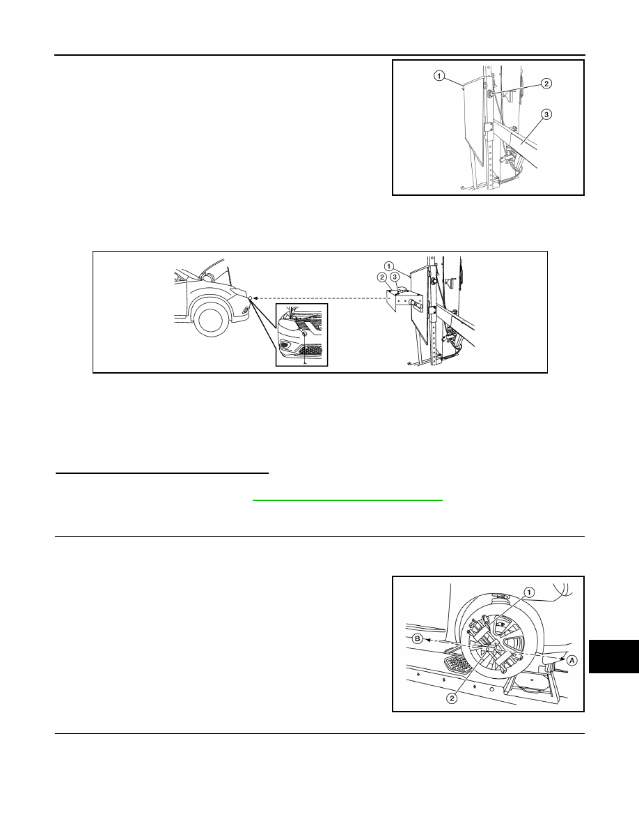
1. Install the wheel adapter (1) on the right front wheel.

2. Mount the laser assembly (2) to the wheel adapter (1) as shown

in the figure.

NOTE:

When the power switch is turned ON, the front laser signal (A)

will be emitted toward the front distance sensor target board,

and the rear laser signal (B) will be emitted toward the rear of

the vehicle.

>> GO TO 3.

3.

SETTING UP STATIONARY TARGET

ALOIA0115ZZ

AWOIA0055ZZ

ALOIA0118ZZ

DAS-76

< BASIC INSPECTION >

[DRIVER ASSISTANCE SYSTEM]

DISTANCE SENSOR ALIGNMENT

1. Place the stationary target next to the right rear tire as shown in

the figure.

2. Turn the laser assembly ON allowing the laser beam to be emit-

ted through the front and rear laser assembly openings.

3. Measure and record the distance (D

r

) between the edge of the

right rear wheel and the laser beam (1) on the stationary target

(horizontal line).

4. Measure and record the height (H

r

) between the laser beam (1)

on the stationary target and ground level (vertical line).

5. Measure and record the distance (D

f

) between the edge of the

right front wheel and the laser beam signal/opening (1) on the

laser assembly (horizontal line).

6. Measure and record the height (H

f

) between the laser beam sig-

nal/opening (1) on the laser assembly and ground level (vertical

line).

NOTE:

•  Horizontal adjustment [front distance (D

f) 

and rear distance

(D

r

)] is accomplished by slowly turning the steering wheel until

the 2 distances are the same.

•  Vertical adjustment [front height (H

f) 

and rear height (H

r

)] is

accomplished by rotating the laser assembly around its axis

until the two heights are the same.

•  Directional arrows (A) and (B) are shown to illustrate the direction of the laser assembly beams.

7. Adjust laser beam as necessary until the two distances match and the two heights match.

NOTE:

You will have to verify both horizontal and vertical adjustments anytime one adjustment is made.

>> Refer to 

DAS-76, "Setting The Distance Sensor Target Board"

.

Setting The Distance Sensor Target Board

INFOID:0000000011277214

DESCRIPTION

Accurate adjustment of the radar alignment requires that the distance sensor target board be accurately posi-

tioned. 

CAUTION:

If the radar alignment is adjusted with the distance sensor target board in the incorrect position, the

distance system will not function properly or the alignment procedure may not be completed success-

fully. 

1.

DISTANCE SENSOR TARGET BOARD FINAL SETTING

1. With the distance sensor target board arm extended, the laser

beam (1) emitted by the laser assembly (A) will be reflected

back (B) toward the laser assembly.

NOTE:

When adjusted properly, reflected laser beam (B) must align

with emitted laser beam (A) and the two laser beams will be

seen as one.

2. Rotate the distance sensor target board to achieve the neces-

sary horizontal adjustment.

3. Adjust the distance sensor target board leveling screws to

achieve the necessary vertical adjustment.

ALOIA0114ZZ

ALOIA0123ZZ

ALOIA0120ZZ

DAS

DISTANCE SENSOR ALIGNMENT

DAS-77

< BASIC INSPECTION >

[DRIVER ASSISTANCE SYSTEM]

C

D

E

F

G

H

I

J

K

L

M

B

N

P

A

4. The figure shown illustrates the laser beam (A) emitted by the

laser assembly (1) and its reflection (B) off of the distance sen-

sor target board arm.

>> GO TO 2.

2.

CHECK THE POSITION OF THE DISTANCE SENSOR TARGET BOARD

Do not place anything other than the distance sensor target board in the space shown in front of the vehicle

(view from top). 

>> Refer to 

DAS-77, "Distance Sensor Adjustment"

Distance Sensor Adjustment

INFOID:0000000011277215

DESCRIPTION

The radar alignment is performed automatically with CONSULT. 

CAUTION:

Perform all necessary work for radar alignment until the adjustment completes as shown in the proce-

dure. If the procedure does not complete, the FCW system is inoperable.

1.

PERFORM RADAR ALIGNMENT

1. Start the engine.

2. Connect CONSULT and select “Work support” of “LASER/RADAR”. 

3. Select “MILLIWAVE RADAR ADJUST” after the “Work support” screen is displayed. 

NOTE:

Confirm the following items;

• The target should be accurately placed.

• The vehicle should be stopped.

4. Select “Start” after the “MILLIWAVE RADAR ADJUST” screen is displayed. 

CAUTION:

Never select “Start” when the target is not accurately placed.

5. Select “Start” after the preparation information is displayed. 

6. Select “Next” after the “Starting alignment.” screen is displayed. 

ALOIA0119ZZ

1.

Distance sensor target board arm

2.

Distance sensor target board

3.

Distance sensor

4.

Vehicle

A

.

Distance between front wheel and la-
ser beam (D

f)

B.

Distance between rear wheel and 
laser beam (D

r)

C.

Height between front laser beam 
and ground (H

f)

D.

Height between rear laser beam and 
ground (H

r)

E.

Distance sensor target board 
center position (Position 2)

L.

1 - 1.5 m (39.3 - 59 in.)

ALOIA0050ZZ

DAS-78

< BASIC INSPECTION >

[DRIVER ASSISTANCE SYSTEM]

DISTANCE SENSOR ALIGNMENT

NOTE:

If the radar is in alignment at this time, “Alignment in progress” is displayed. It may take several 10s of

seconds until the result is displayed.

7. Confirm the displayed item.

-

“Alignment completed.”: Go to 8.

-

Except “Alignment completed.”: Perform the following services.

NOTE:

Replace Distance sensor if “Sensor malfunction.” is repeatedly indicated.

8. Confirm displayed value.

-

Within reference value: Go to 9.

-

Outside of reference value: Check the target board condition and perform radar alignment again.

NOTE:

Check the condition of the Distance sensor installation.

Check the vehicle for damage.

Replace Distance sensor if it is outside the reference value, even when Distance sensor installation is

installed normally and the vehicle is not damaged.

9. Select “OK” after the “No error detected.” is displayed. 

10. Select “OK” after the “End of alignment.” is displayed.

CAUTION:

Once “MILLIWAVE RADAR ADJUST” is started with CONSULT, always continue the work until the

horizontal radar alignment is completed successfully. If the job is stopped midway, the radar align-

ment is not adjusted and the FCW system cannot operate. 

>> RADAR ALIGNMENT END

Displayed item

Possible cause

Service procedure

Alignment condition is not ready.

• DTC is detected (Except C1A12).
• The position of the Distance sensor target 

board is not correct.

• Vehicle is moving.

Check the vehicle condition and perform ra-
dar alignment again.

Alignment condition is not ready. 
(Stop the vehicle.)

Vehicle is moving.

Stop the vehicle and perform radar align-
ment again.

Target is not detected.

• A target is not-yet-placed.

(The Distance sensor cannot detect target)

• The position of the Distance sensor target 

board is not correct.

• The position of the Distance sensor is not cor-

rect.

Check the target board condition and per-
form radar alignment again.

Sensor malfunction.

Distance sensor malfunction.

Check the vehicle condition and perform ra-
dar alignment again.

Displayed item

Monitor item

Reference value

Alignment completed.

FACTORY AIM L/R

Less than 3.00 deg

FACTORY AIM U/D

Less than 3.00 deg

AIMING VALUE L/R

Less than 3.00 deg

AIMING VALUE U/D

Less than 3.00 deg


Content   ..  224  225  226  227   ..