Nissan Rogue. Manual - part 176
VDC OFF SWITCH
BRC-115
< DTC/CIRCUIT DIAGNOSIS >
[VDC/TCS/ABS]
C
D
E
G
H
I
J
K
L
M
A
B
BRC
N
O
P
VDC OFF SWITCH
Component Function Check
INFOID:0000000011280646
1.
CHECK VDC OFF SWITCH OPERATION
Check that VDC OFF indicator lamp in combination meter turns ON/OFF when VDC OFF switch is operated.
Is the inspection result normal?
YES
>> Inspection End.
NO
>> Proceed to
BRC-115, "Diagnosis Procedure"
.
Diagnosis Procedure
INFOID:0000000011280647
1.
CHECK VDC OFF SWITCH CIRCUIT
1. Turn the ignition switch OFF.
2. Disconnect ABS actuator and electric unit (control unit) harness connector.
3. Disconnect VDC OFF switch harness connector.
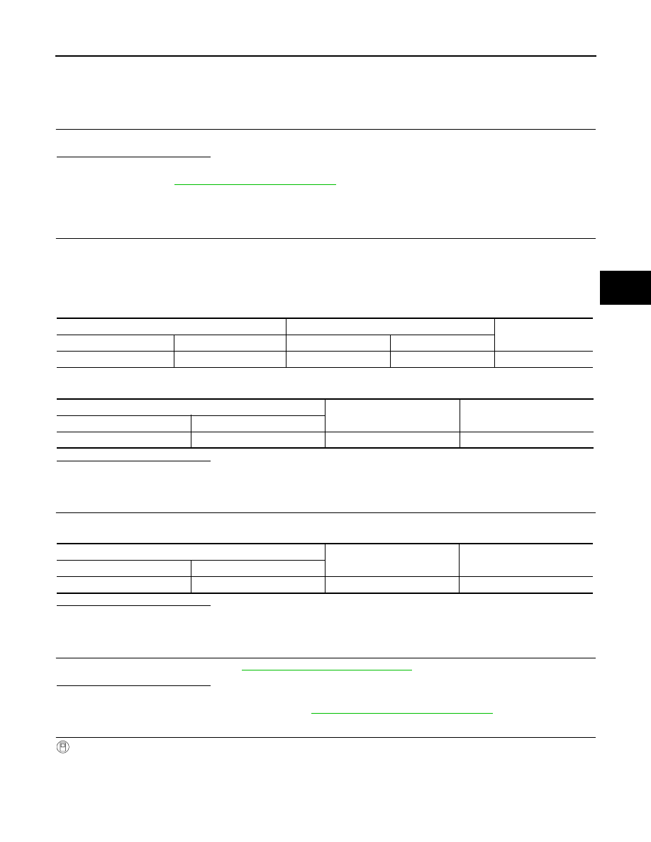
4. Check the continuity between ABS actuator and electric unit (control unit) harness connector and VDC
OFF switch harness connector.
5. Check the continuity between ABS actuator and electric unit (control unit) harness connector and ground.
Is the inspection result normal?
YES
>> GO TO 2.
NO
>> Repair or replace error-detected parts.
2.
CHECK VDC OFF SWITCH GROUND CIRCUIT
Check the continuity between VDC OFF switch harness connector and ground.
Is the inspection result normal?
YES
>> GO TO 3.
NO
>> Repair or replace error-detected parts.
3.
CHECK VDC OFF SWITCH
Check the VDC OFF switch. Refer to
BRC-116, "Component Inspection"
.
Is the inspection result normal?
YES
>> GO TO 4.
NO
>> Replace the VDC OFF switch. Refer to
BRC-136, "Removal and Installation"
.
4.
CHECK VDC OFF SWITCH SIGNAL
With CONSULT
1. Connect ABS actuator and electric unit (control unit) harness connector.
2. Connect VDC OFF switch harness connector.
3. Select “ABS”, “Data Monitor” and “OFF SW” according to this order. Check the VDC OFF switch signal.
ABS actuator and electric unit (control unit)
VDC OFF switch
Continuity
Connector
Terminal
Connector
Terminal
E125
15
M79
6
Yes
ABS actuator and electric unit (control unit)
—
Continuity
Connector
Terminal
E125
15
Ground
No
VDC OFF switch
—
Continuity
Connector
Terminal
M79
8
Ground
Yes