Nissan Rogue. Manual - part 1194


  Index      Nissan     Nissan Rogue (2015 year) - Service and Repair Manual


Search            


Content   ..  1192  1193  1194  1195   ..


Nissan Rogue. Manual - part 1194


TM-148

< DTC/CIRCUIT DIAGNOSIS >

[CVT: RE0F10D]

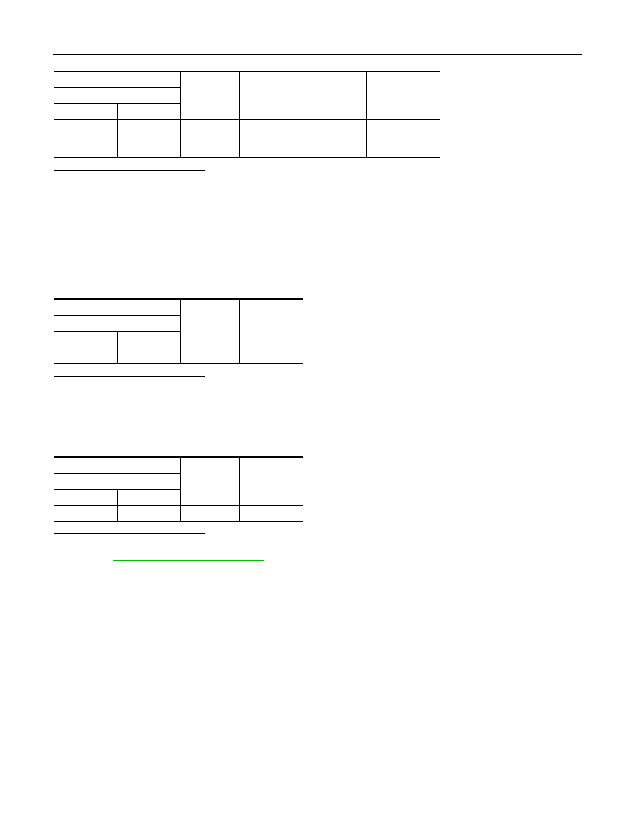
P0848 TRANSMISSION FLUID PRESSURE SEN/SW B

Is the inspection result normal?

YES >> INSPECTION 

END

NO

>> GO TO 2.

2.

CHECK SECONDARY PRESSURE SENSOR POWER CIRCUIT

1. Turn ignition switch OFF.

2. Connect TCM connector.

3. Disconnect CVT unit connector.

4. Turn ignition switch ON.

5. Check voltage between CVT unit harness connector terminal and ground.

Is the inspection result normal?

YES 

>> GO TO 3.

NO

>> Repair or replace malfunctioning parts.

3.

CHECK SECONDARY PRESSURE SENSOR SIGNAL CIRCUIT

Check voltage between CVT unit harness connector terminal and ground.

Is the inspection result normal?

YES  >> There is malfunction of secondary pressure sensor. Replace transaxle assembly. Refer to 

TM-

220, "Removal and Installation"

.

NO

>> Repair or replace malfunctioning parts.

+

Condition

Voltage

TCM

Connector

Terminal

F75

16

Ground

• After engine warm up
• Selector lever: “N” position
• At idle

1.23 – 1.25 V

+

Voltage

(Approx.)

CVT unit

Connector

Terminal

F74

22

Ground

5.0 V

+

Voltage

(Approx.)

CVT unit

Connector

Terminal

F74

14

Ground

0 V

P084C TRANSMISSION FLUID PRESSURE SEN/SW H

TM-149

< DTC/CIRCUIT DIAGNOSIS >

[CVT: RE0F10D]

C

E

F

G

H

I

J

K

L

M

A

B

TM

N

O

P

P084C TRANSMISSION FLUID PRESSURE SEN/SW H

DTC Description

INFOID:0000000011279369

DTC DETECTION LOGIC

POSSIBLE CAUSE

• Harness or connector (Primary pressure sensor circuit is open or shorted to ground) 

• Primary pressure sensor 

• Control valve assembly

FAIL-SAFE

Not changed from normal driving

DTC CONFIRMATION PROCEDURE

1.

PREPARATION BEFORE WORK

If another "DTC CONFIRMATION PROCEDURE" occurs just before, turn ignition switch OFF and wait for at

least 10 seconds, then perform the next test.

>> GO TO 2.

2.

CHECK DTC DETECTION

With CONSULT

1. Start the engine.

2. Select “Data Monitor” in “TRANSMISSION”.

3. Select “FLUID TEMP”.

4. Maintain the following conditions for 10 seconds or more.

5. Check the first trip DTC.

With GST

1. Start the engine and wait for at least 10 seconds.

CAUTION:

When the ambient temperature is less than 

20°C (4°F) and the engine is cold, warm up the

engine for approximately 5 minutes. 

2. Check the first trip DTC.
Is “P084C”detected?

YES

>> Go to 

TM-149, "Diagnosis Procedure"

.

NO-1 >> To check malfunction symptom before repair: Refer to 

GI-44, "Intermittent Incident"

.

NO-2 >> Confirmation after repair: INSPECTION END

Diagnosis Procedure

INFOID:0000000011279370

1.

CHECK TCM INPUT SIGNALS

1. Turn ignition switch OFF.

2. Start the engine.

3. Check voltage between TCM harness connector terminals. 

DTC

CONSULT screen terms

(Trouble diagnosis content)

DTC detection condition

P084C

FLUID PRESS SEN/SW H
(Transmission Fluid Pressure Sensor/Switch H 
Circuit Low)

When all of the following conditions are satisfied and this state is main-
tained for 5 seconds:
• CVT fluid temperature: More than 

−20°C (−4°F)

• TCM power supply voltage: More than 11 V
• Primary pressure sensor voltage: 0.09 V or less

FLUID TEMP

: More than 

−20°C (−4°F)

TM-150

< DTC/CIRCUIT DIAGNOSIS >

[CVT: RE0F10D]

P084C TRANSMISSION FLUID PRESSURE SEN/SW H

Is the inspection result normal?

YES >> INSPECTION 

END

NO

>> GO TO 2.

2.

CHECK CIRCUIT BETWEEN TCM AND CVT UNIT (PART 1)

1. Turn ignition switch OFF.

2. Disconnect TCM connector and CVT unit connector.

3. Check continuity between TCM harness connector terminals and CVT unit harness connector terminals.

Is the inspection result normal?

YES 

>> GO TO 3.

NO

>> Repair or replace malfunctioning parts.

3.

CHECK CIRCUIT BETWEEN TCM AND CVT UNIT (PART 2)

Check continuity between TCM harness connector terminals and ground.

Is the inspection result normal?

YES  >> There is malfunction of primary pressure sensor. Replace transaxle assembly. Refer to 

TM-220,

"Removal and Installation"

.

NO

>> Repair or replace malfunctioning parts.

+

Condition

Voltage

TCM

Connector

Terminal

F75

17

Ground

• After engine warm up
• Selector lever: “N” position
• At idle

0.75 – 0.82 V

TCM

CVT unit

Continuity

Connector

Terminal

Connector

Terminal

F75

11

F74

18

Existed

17

13

26

22

TCM

Continuity

Connector

Terminal

F75

17

Ground

Not existed

26

P084D TRANSMISSION FLUID PRESSURE SEN/SW H

TM-151

< DTC/CIRCUIT DIAGNOSIS >

[CVT: RE0F10D]

C

E

F

G

H

I

J

K

L

M

A

B

TM

N

O

P

P084D TRANSMISSION FLUID PRESSURE SEN/SW H

DTC Description

INFOID:0000000011279371

DTC DETECTION LOGIC

POSSIBLE CAUSE

• Harness or connector (Primary pressure sensor circuit is open or shorted to ground)

• Primary pressure sensor

• Control valve assembly

FAIL-SAFE

Not changed from normal driving

DTC CONFIRMATION PROCEDURE

1.

PREPARATION BEFORE WORK

If another "DTC CONFIRMATION PROCEDURE" occurs just before, turn ignition switch OFF and wait for at

least 10 seconds, then perform the next test.

>> GO TO 2.

2.

CHECK DTC DETECTION

With CONSULT

1. Start the engine.

2. Select “Data Monitor” in “TRANSMISSION”.

3. Select “FLUID TEMP”.

4. Maintain the following conditions for 10 seconds or more.

5. Check the first trip DTC.

With GST

1. Start the engine and wait for at least 10 seconds.

CAUTION:

When the ambient temperature is less than 

20°C (4°F) and the engine is cold, warm up the

engine for approximately 5 minutes. 

2. Check the first trip DTC.
Is “P084D”detected?

YES

>> Go to 

TM-151, "Diagnosis Procedure"

.

NO-1 >> To check malfunction symptom before repair: Refer to 

GI-44, "Intermittent Incident"

.

NO-2 >> Confirmation after repair: INSPECTION END

Diagnosis Procedure

INFOID:0000000011279372

1.

CHECK TCM INPUT SIGNALS

1. Turn ignition switch OFF.

2. Start the engine.

3. Check voltage between TCM harness connector terminals. 

DTC

CONSULT screen terms

(Trouble diagnosis content)

DTC detection condition

P084D

FLUID PRESS SEN/SW H
(Transmission Fluid Pressure Sensor/Switch 
“H” Circuit High)

When all of the following conditions are satisfied and this state is main-
tained for 5 seconds:
• CVT fluid temperature: More than 

−20°C (−4°F)

• TCM power supply voltage: More than 11 V
• Primary pressure sensor voltage: 4.7 V or more

FLUID TEMP

: More than 

−20°C (−4°F)


Content   ..  1192  1193  1194  1195   ..